Assembly is one of the nicest tools you can make use of while using Solidworks. We are going to use an easy example to help wrap our head around this command in minutes.
Let’s get to the most important.
Solidworks assembly
Assembly roughly speaking help you make a complex model made of other models previously created. Let’s see how that works.
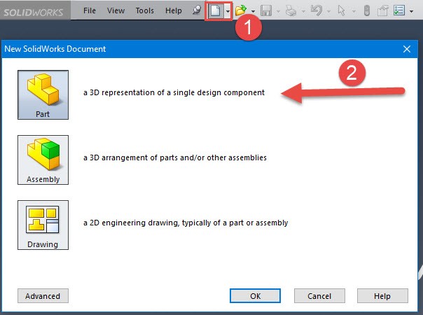
Step 1
Our usual first step which I would not spend too much time on.
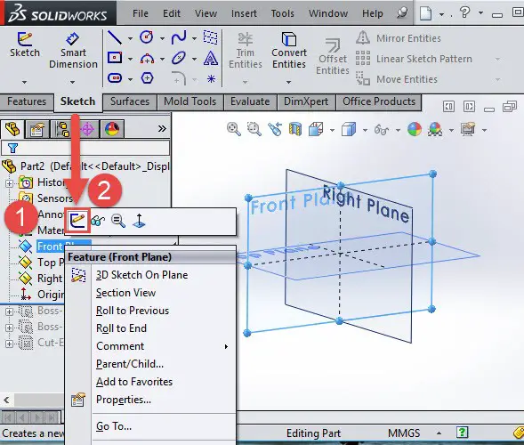
Step 2
Our plane will be the Front Plane.
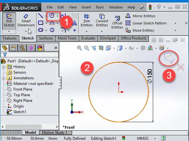
Step 3
Create a Circle with its origin set at the origin of the sketch, click on Smart Dimension and give 150 mm as a diameter.
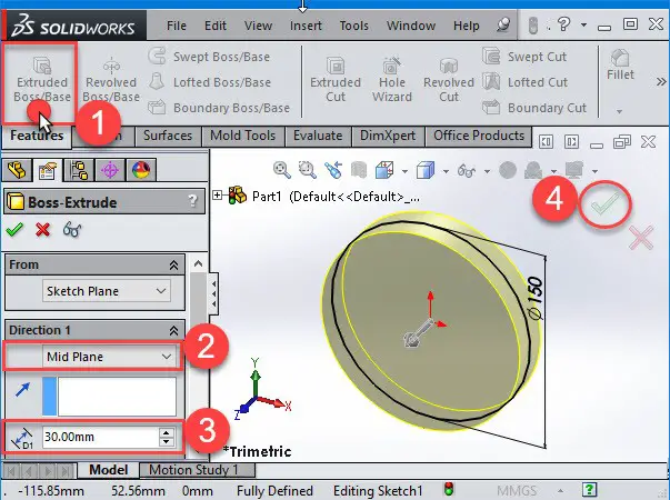
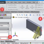
Step 4
Select Extruded Boss/Base, give 30 mm thickness with the direction set to Mid Plane and click on Okay.
Step 5
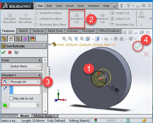
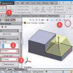
Now create a new sketch on the Extrude Boss surface, create a Circle as shown below with 40 mm of diameter.
Now use the circle to make an Extruded Cut on the top face of the disk. Change your view to Isometric View, select Extruded Cut, select the Sketch and select Through All.
Step 6
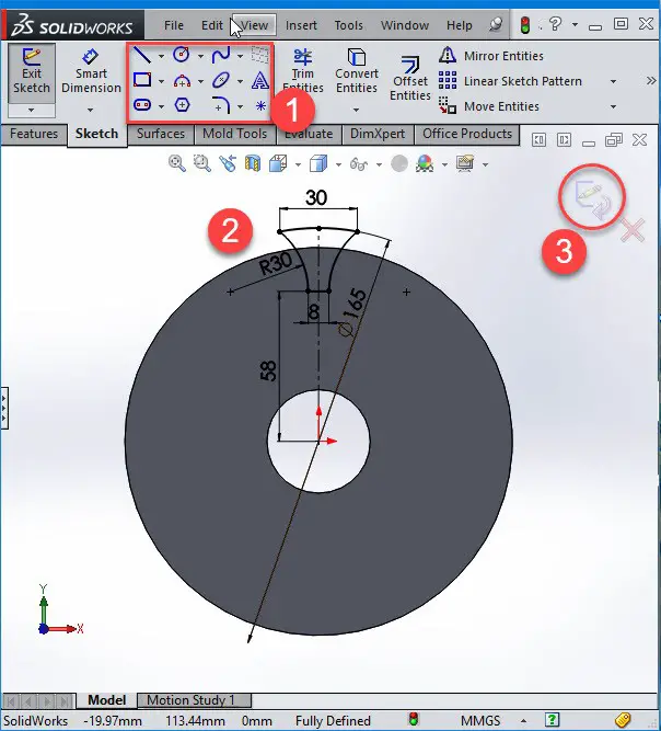
Create a new sketch on the Extrude Boss surface, draw a sketch similar to the on the picture below, Extrude Cut and select Through All.
Step 7
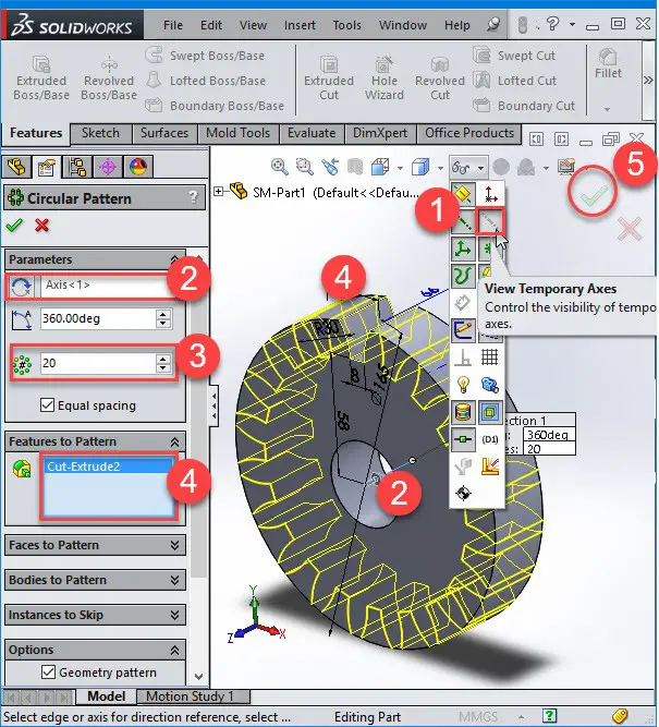
Now, we are going to use the circular pattern made of the cut we’ve just create and distribute it 20 times around the disk. The Circular pattern needs an axes of revolution which is the center of our base. To activate this axis, Select VIEW at the top then choose Temporary Axis as you see below.
You probably won’t be able to see the axis unless you ZOOM in and look more carefully at the origin. At the end, save your file with name: SM-Part1
Step 8
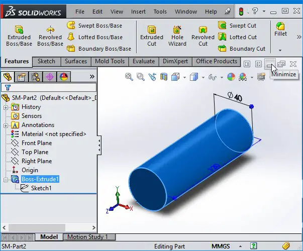
Now, we are going to create a shaft.
Open a new part and select the Front Plane, draw a circle with D = 40 mm and extrude it with a length of 120 mm using the Mid Plane direction. Then save it with the name: SM-Part2
Step 9
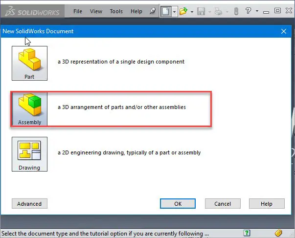
Now create a new assembly environment.
Step 10
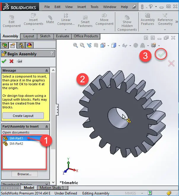
As you can see, Solidworks shows the two models that we’ve created; SM-Part1 and SM-Part2.
The first model you import into the graphic view is fixed by the software. Therefore, we normally import the main model first and secondly the other, and do not forget to validate.
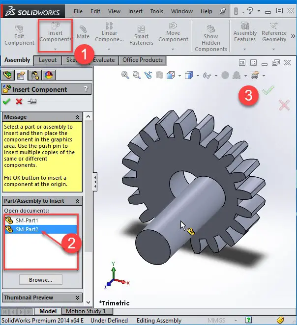
Step 11
We are going to import the shaft. Click on Insert Components, select SM-Part2 and click on green tick.
Step 12
Now we have both models in assembly but they are still separate entities. In this
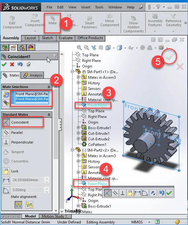
Now, we are going to assemble the models using the Mate commands. After selecting the Mate command, select the shaft surface and the hole.
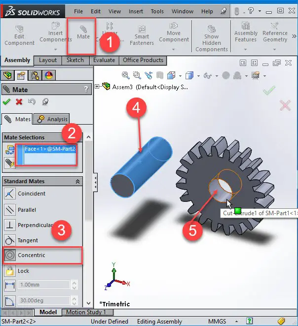
Step 13
Now, we want to put the shaft in the middle of gear. There are different ways to do this:
- We can use the Mate command to make the shaft fit in the middle of gear.
- We can use the Coincident Standard Mates features to make the shaft dimensions to coincide with the hole in the middle of the gear.
That has just been a quick tutorial to illustrate how to Assemble in Solidworks.
You might also like:
- Solidworks Equation
- Solidworks Tutorial: Sheet Metal
- How to Create a Sphere in Solidworks
- SolidWorks Tutorial: Extrude
- Solidworks Tutorial: Assembly
- Solidworks Tutorial: Cosmetic Thread
- Solidworks Tutorial: How to Draw a Coke Bottle
- Solidworks Tutorial: Easy to Follow 3D Sketching Using Solidworks
- Solidworks Tutorial: Convert Entities
- SolidWorks Tutorial: SWEEP
Related posts:
 Solidworks Tutorial: Circular Pattern
 Solidworks Tutorial: How to Mirror Parts
 AutoCAD vs SolidWorks – Which One Is The Best?
 Solidworks Tutorial: Convert Entities
 Scrutinizing CATIA vs SolidWorks
 7 Free Alternatives to SolidWorks Every Student Should Know
 Comparing Pro Engineer vs SolidWorks
 The Best Graphics Card For SolidWorks