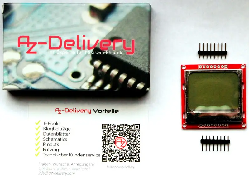
The Philips PCD8544 driver chip is connected to a recycled screen from the popular Nokia 5110 phone. Because the screens are second-hand, the glass cover often has small scratches/blemishes.
They are rehoused in a metal box on a PCB with 8 connections. You need to solder on the supplied pins. The screen is a Liquid Crystal Display, LCD.
You can obtain a copy of the documentation for the driver chip from here and here.
AZ Delivery supply a free, 9-page pdf guide to using the device.
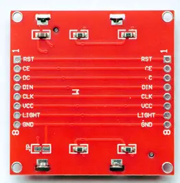
If we look more closely at the board, we find that the 8 connection pins are labeled on the bottom surface, and there appear to be 4 resistors near each of the LEDs, illuminating the screen from the sides.
The two sets of pads are interconnected so you can use either set. (Other suppliers of similar boards do not include resistors, which need to be added to the input line by the user. With these boards, you can control the brightness with a PWM pin supplying power to the LEDs. The connections on such boards may be in a different order – beware!)
There appear to be jumper pads (JP) linking something to GND, but the documentation has no information.
Important! This is a 3.3V device and will be damaged if connected directly to 5V.
| Pin: Description | Additional information |
| 1 RST (Reset ) | Input |
| 2 CE (Chip Enable) | Input |
| 3 DC (Data/Control) | Input |
| 4 DIN (Data in) | Input |
| 5 CLK (Clock) | Input |
| 6 VCC | Power supply – max. 3.3V! |
| 7 LIGHT | LED active when connected to GND |
| 8 GND (Ground) | Ground |
The AZ Delivery documentation gives a Fritzing circuit showing the connections to an Arduino UNO using voltage shifters to protect the display.
This involves a great deal of wiring and extra expense for the voltage shifters.
A more compact and cheaper arrangement is to connect the data lines with 10K Ohm protection resistors as shown below. Make sure that VCC goes to the 3.3V outlet on the Arduino UNO.
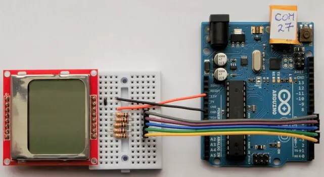
The simplest solution would be to use a 3.3V Arduino microcontroller with direct connection.
| Display Pin | Comment | UNO Pin |
| 1 RST (Reset ) | Input | 3 |
| 2 CE (Chip Enable) | Input | 4 |
| 3 DC (Data/Control) | Input | 5 |
| 4 DIN (Data in) | Input | 6 |
| 5 CLK (Clock) | Input | 7 |
| 6 VCC | Max. 3.3V! | 3.3V |
| 7 LIGHT | To GND on breadboard | GND |
| 8 GND (Ground) | Ground | GND |
With the black link between pins 7 & 8 the LEDs are always on.
The documentation gives an example sketch to write pixels directly to the display using commands to the PCD8544. This is a pretty advanced method of driving the display and very a tedious method of creating images. You have to count pixels on graph paper and calculate the values of bytes.
// Control Nokia 5110 LCD Display
// AZDelivery Example script
#define CLK 7 // More convenient pins
#define DIN 6
#define DC 5
#define CE 4
#define RST 3
static const byte LOGOTBL[] = { //AZ Delivery Bitmap Logo
0x0F,0x5,0x5,0x0F,0x90,0xD0,0xB0,0x90,0x00,0x00,0x08,0x08,0x08,0x08,0x00,
0x00,0xFF,0x81,0x81,0x81,0x81,0x7E,0x00,
0xFF,0x89,0x89,0x81,0x81,0x81,0x00,0xFF,0x80,0x80,0x80,0x80,0x80,0x00,
0xFF,0x00,0x07,0x38,0xC0,0xC0,0x38,0x07,
0x00,0xFF,0x89,0x89,0x81,0x81,0x81,0x00,0xFF,0x09,0x19,0x29,0x49,0x86,
0x00,0xF,0x90,0x90,0x90,0x90,0xF7
};
// Functions
void LcdWriteCmd(byte order) { // Send command to display
digitalWrite(DC, LOW); // DC Pin is LOW for commands to the display
shiftOut(DIN, CLK, MSBFIRST, order); // Transmit data byte serially
// with MSB (most significant byte) first
}
void LcdWriteData(byte data) { // Send data to display
digitalWrite(DC, HIGH); // DC Pin is HIGH for data to the display
shiftOut(DIN, CLK, MSBFIRST, data); // Transmit data byte serial
// with MSB (most significant byte) first
}
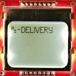
void LcdWriteLogo() {
digitalWrite(CE, LOW); // Chip Enable Pin is LOW,
// data transfer is activated
LcdWriteCmd(0x80); // Jump to row 0 column 0, Jump Column
LcdWriteCmd(0x40); // Skip row
// Clear screen completely
for(int i=0; i < 504; i++) {
LcdWriteData(0x00); // Delete complete display
}
// Output AZ logo
for(int i=0; i < 66; i++) {
LcdWriteData(LOGOTBL[i]); // Write logo data into display
}
digitalWrite(CE, HIGH); // Chip Enable Pin is HIGH,
// data transfer is deactivated
}
void setup() {
pinMode(CLK, OUTPUT); // Switch pin to output
pinMode(DIN, OUTPUT); // Switch pin to output
pinMode(DC, OUTPUT); // Switch pin to output
pinMode(CE, OUTPUT); // Switch pin to output
pinMode(RST, OUTPUT); // Switch pin to output
digitalWrite(RST, HIGH); // Reset signal to Nokia display
delay(100);
// forward
digitalWrite(RST, LOW);
delay(100);
digitalWrite(RST, HIGH);
delay(100);
// Initialization of the display according to data sheet
digitalWrite(CE, LOW); // Chip Enable Pin is LOW,
// data transfer is activated
LcdWriteCmd(0x21); // Extended command set LCD
LcdWriteCmd(0x90); // set LCD Vop
LcdWriteCmd(0x20); // Normal command LCD
LcdWriteCmd(0x0C); // LCD Normal Mode
digitalWrite(CE, HIGH); // Chip Enable Pin is HIGH,
// data transfer is deactivated
}
void loop() {
LcdWriteLogo();
delay(20000);
}On executing the script, I was pretty disappointed at this point as nothing appeared on the screen.
I looked in the datasheet and found that it was possible to change Vop (operational voltage?) and Bias.
I replaced
LcdWriteCmd(0x90); // set LCD VopWith these 3 lines and ran the script again.
LcdWriteCmd(0xBF); // set LCD Vop
LcdWriteCmd(0x04); // Set Temp coefficient
LcdWriteCmd(0x13); // Bias mode 1:40
The expected display appeared.
The method works but we need to find an easier method of obtaining the bytes for a screen image. I decided to use Paint.net, to create the image, and LCDAssistant to convert a bitmap file to a list of bytes.
Starting with Paint.net (This could also be done using MS paint)

I defined a drawing area of 84 pixels wide and 48 pixels high. I disabled Antialiasing, added a star shape and some text to make a test piece. I saved the image as a bitmap with automatic depth.
I then loaded the saved image into LCDAssistant and used these settings.
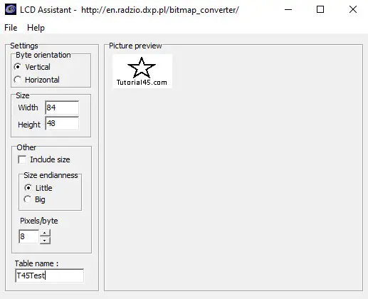
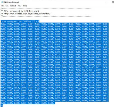
I saved this to create another file called T45Test, which I then opened in Notepad.
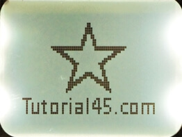
I replaced the data block in the original script, and adjusted this loop to cope with the extra data and name change.
// Output Image
for(int i=0; i < 504; i++) {
  LcdWriteData(T45Test[i]); // Write logo data into display
 }
This quickly produced the expected display.
What we need to be able to do now is write words, graphic elements and numbers to the screen in real-time under program control. Luckily there is an Adafruit library for this device to provide the necessary help.
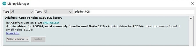
This library is used with the Adafruit GFX library installed earlier on my computer for another project. Install any dependencies indicated as well. Try the long example script that comes with the library. It may well lack contrast initially.
The library handles contrast (Vop) and Bias slightly differently so I wrote a short script to allow investigation of the best settings to overcome the poor contrast.
// Set up screen visibility PCD8544 & Nokia 5110 screen
// Tony Goodhew 9th July 2020
// Tutorial45.com
#include <SPI.h>
#include <Adafruit_GFX.h>
#include <Adafruit_PCD8544.h>
// PINS CLK, DIN, DC, CE, RST
Adafruit_PCD8544 display = Adafruit_PCD8544(7, 6, 5, 4, 3);
void setup() {
Serial.begin(9600);
display.begin(); // Initialise display
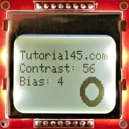
int con = 56; // Change up or down by 1 to get
int bias = 4; // the best settings for your display
display.setBias(bias);
display.setContrast(con);
display.clearDisplay();
display.setCursor(0,5); // INCLUDE ABOVE AT START OF YOUR OWN SCRIPTS
display.println("Tutorial45.com");
display.setCursor(0,15);
display.print("Contrast: ");
display.println(con);
display.setCursor(0,25);
display.print("Bias: ");
display.println(display.getBias());
display.fillCircle(68, 36, 11, BLACK);
display.fillCircle(68, 36, 6, WHITE);
display.display(); // Essential instruction to update visible display
}
void loop() {}Settings of con = 56 and bias = 4 gave the best contrast without activating the background (white) pixels on my display. Just try running the script with single unit changes to the values of con and bias until you get good visibility.
Now that the contrast has been fixed, we can see that the display has a slight aspect ratio ‘feature’ and circles appear as ellipses. The lower pixel count means that there is less space to write and draw when compared to other LCD displays – especially when compared with the SSD1306 128×64 display. However, the screen size and pixels are larger aiding visibility from a greater distance.
SSD1306 128×64 = 8192 pixels
SSD1306 128×32 = 4086 pixels
Nokia 86×48 = 4032 pixels
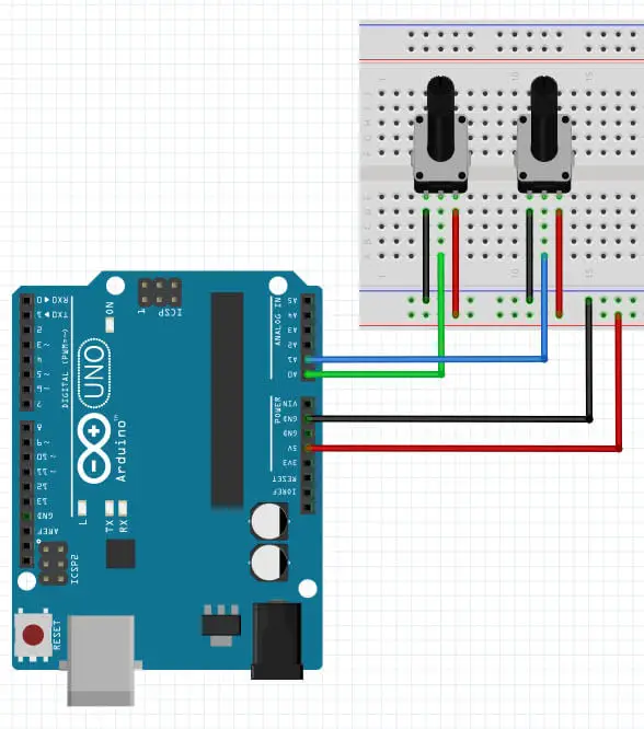
We are now ready to check how quickly the screen updates in a useful application. I added a 10K Ohm potentiometer on A0 to provide an input to the script. (You will need 2 potentiometers for a later script.)
// Volt Meter on Nokia 5110
// Tony Goodhew 9th July 2020
// Turorial45.com
// 10K Ohm potentiometer on A0
#include <SPI.h>
#include <Adafruit_GFX.h>
#include <Adafruit_PCD8544.h>

//   PINS                                   CLK, DIN, DC, CE, RST
Adafruit_PCD8544 display = Adafruit_PCD8544(7,   6,   5,  4,  3);

int sensorPin = A0;   // select the input pin for the potentiometer
int sensorValue = 0;  // variable to store the value coming from the sensor

void setup()   {
  Serial.begin(9600);
  display.begin();      // Initialise display
  int con = 56;         // Change up or down by 1 to get
  int bias = 4;         // the best settings for your display
  display.setBias(bias);
  display.setContrast(con);
  display.clearDisplay();
  display.setCursor(0,5);
  display.println("Tutorial45.com");
  display.setCursor(0,15);
  display.print("Volt Meter");
  display.setCursor(17,40);
  display.print("Volts:");
  display.display();  // Static parts of screen written at this point
}

int bar(int v, float vv) {  // Bar graph
  display.drawLine(0,28,0,40, BLACK);
  display.fillRect(1,30,80,8,WHITE);   // Rub out old bar graph
  display.fillRect(0,30,v,8,BLACK);    // Write new bar graph
  display.fillRect(55,40,26,10,WHITE); // Rub out old text
  display.setCursor(55,40);
  display.print(vv);                   // Write new text
  display.display();                   // Update display
}
// ++++++++++++Main Loop ++++++++++++++
void loop() {
  // Read pot and display values
  sensorValue = analogRead(sensorPin); // Read the value from the sensor
  float volts = (sensorValue * 5.0 / 1023.0);  // Calculate voltage
  int x = float(sensorValue * 80.0/1023);     // Calculate percentage
  bar(x,volts);  // Redraw bar graph
  delay(100);      // Delay to reduce jitter
}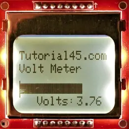
Twisting the knob of the potentiometer changes the length of the bar and updates the voltage value. Notice the slight scratch marks on the bottom left corner of the bar graph.
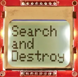
Nokia 5110 Arduino Project with the AZ-Delivery with PCD8544 84×48 Pixel LCD Display
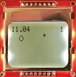
This project illustrates how the display can be changed under the control of a couple of 10K Ohm potentiometers. The potentiometers control the left/right and up/down position of a circular sight in which the player moves to cover the target, indicated by a small cross. As soon as the centers are identical the ‘target’ is destroyed and another target appears at a random position. There are 5 targets in a game. The search time is recorded and displayed at the end of the game.
// Game on Nokia 5110 – Search and Destroy
// Tony Goodhew 12th July 2020
// Turorial45.com
// 10K Ohm potentiometers on A0 and A1
#include <SPI.h>
#include <Adafruit_GFX.h>
#include <Adafruit_PCD8544.h>

//   PINS                                   CLK, DIN, DC, CE, RST
Adafruit_PCD8544 display = Adafruit_PCD8544(7,   6,   5,  4,  3);

int xPin = A0;   // x potentiometer
int yPin = A1;   // y potentiometer
int ox = 0;      // Old sight position - ring
int oy = 0;
int nx = 20;     // New sight position
int ny = 20;
int tx = 15;     // Target position
int ty = 15;
int count = 0;   // Targets destroyed
float t1 = 0;    // Time increment – for a single target
unsigned long t0;// millis() value when target appears
float total = 0; // Total time spent searching

void setup()   {
  Serial.begin(9600);      // Ready for debugging
  display.begin();         // Initialise display
  int con = 56;            // Change up or down by 1 at a time to get
  int bias = 4;            // the best settings for your display
  display.setBias(bias);
  display.setContrast(con);
  display.clearDisplay();
  display.setTextSize(2);  // Large text for Title screen
  display.setCursor(0, 0);
  display.print("Search");
  display.setCursor(0, 16);
  display.print("and");
  display.setCursor(0, 32);
  display.print("Destroy");
  display.display();
  delay(3000);
  display.setTextSize(1);  // Normal size text for game play
  display.clearDisplay();
}
int target(int x, int y, int c){   // Show target cross
  display.drawLine(x-2,y,x+2,y,c);
  display.drawLine(x,y-2,x,y+2,c);
}
int finish(){                  // Final screen to display total time
  display.clearDisplay();
  display.setTextSize(1);
  display.setCursor(5,5);
  display.print("You took:");
  display.setTextSize(2);
  display.setCursor(20,18);
  display.print(total);
  display.setTextSize(1);
  display.setCursor(0,40);
  display.print(count);
  display.setCursor(8,40);
  display.print(" Targets hit");
  display.display();
  while(1){}                     // Wait for ever - HALT
}
int ring(int x, int y, int c) {  // Draw a ring - sight
  display.drawCircle(x,y,3,c);   // Radius is 3 pixels
}
int blob(int x, int y, int c){   // Fill a ring - target destroyed
  display.fillCircle(x,y,3,c);
}
int flash(int x,int y){          // Flash location of destroyed target
  t1 = ((millis() - t0)/1000.0); // Incremental search time in seconds
  total = total + t1;            // Update total searching time
  randomSeed(int(t1*100.0));     // Improve randomness
  display.clearDisplay();
  display.display();
  display.setCursor(0,0);
  display.print(total);
  count = count + 1;             // Update targets destroyed
  display.setCursor(78,0);       // Show count - top right
  display.print(count);
  display.display();
  for (int i = 0; i<3; i++){     // Flash the blob - A hit!
    blob(x,y,1);
    display.display();
    delay(300);
    blob(x,y,0);
    display.display();
    delay(300);
  }
  t0 = millis();                 // Reset incremental timer
  if (count == 5){finish();}     // Enough targets destroyed?
}
// ++++++++++++Main Loop ++++++++++++++
void loop() {
  target(tx,ty,1);                     // Show target
  nx = 3 + int(analogRead(xPin) /14);  // Get x position of sight
  ny = 43 - int(analogRead(yPin) /31); // Get y position of sight
  ring(ox,oy,0);                       // Blank old sight
  ring(nx,ny,1);                       // Show new sight
  ox = nx;                             // New position becomes old position
  oy = ny;
  display.display();
  if ((ox == tx) & (oy == ty)){ // Is it a hit?
    flash(tx,ty);               // Yes – Explode! Update time and targets hit
    tx = random(76) + 3;        // Get new random target position
    ty = random(33) + 10;
  }
}

Conclusion
This display operates at 3.3 volts, and it necessitates additional setup, such as voltage shifters or 10K resistors, particularly when used with 5-volt boards like the UNO.
Initially, I was not impressed with the limited documentation and the display’s low contrast, but now this device has grown on me. Although its pixel count is quite low, supporting only 6 brief lines of text, its display diagonal is larger than that of the SSD1306 128×64, making it more readable from afar.
It utilizes five data lines, in contrast to the two lines used by I2C devices. Notably, it has a speed sufficient for basic games and provides real-time feedback.
Additional things to try:
- Exchange the simple potentiometer for an analog potentiometer joystick and see if this brings down your overall time with the game.
- Use Paint.net and LCDAssistant to create a series of images to display one after another in a slide show.
- Connect a distance sensor such as an HC-SR04 Ultrasonic or VL53L0X Time of Flight sensor and display the distance as you move your hand back and forth in front of the sensor.
- Add an accelerometer and build a 2-dimensional ‘bubble-level’.
Hint
If your instructions are not appearing on the screen, check that you have ended the sequence with
display.display();This is the essential instruction to force your changes to the screen and it is so easy to forget it.
Related posts:
 Arduino Projects: Building an Arduino Countdown Timer
 Arduino Projects: LED – 4X4X4 LED Cube
 Arduino Projects: PIR Motion Sensor
 The Best Arduino Starter Kits
 Arduino Relay Project
 Arduino Projects: Building a Mini Arduino Shield With KiCAD – Part 1
 Arduino MOSFET Project
 6 Reasons to Build Your Next Arduino Project With XOD