An Anduino LED Cube is a fantastic project; it can be used as a decoration piece or used with other equipment like microphones or motion sensors for various applications. Basically an LED cube is a 3 dimensional cube made out of Light Emitting Diodes (LEDs). The Cube can be made in various ways but for this project, a simple setup is used that is controlled by an Arduino Uno microcontroller.
LED Cube Concept
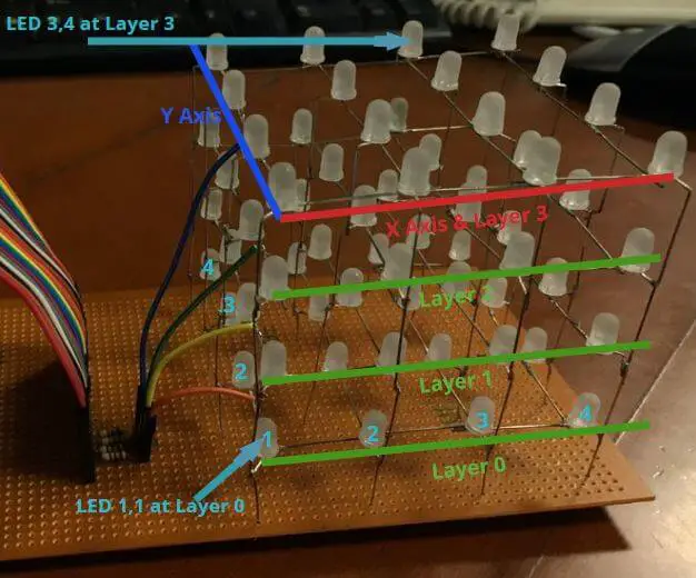
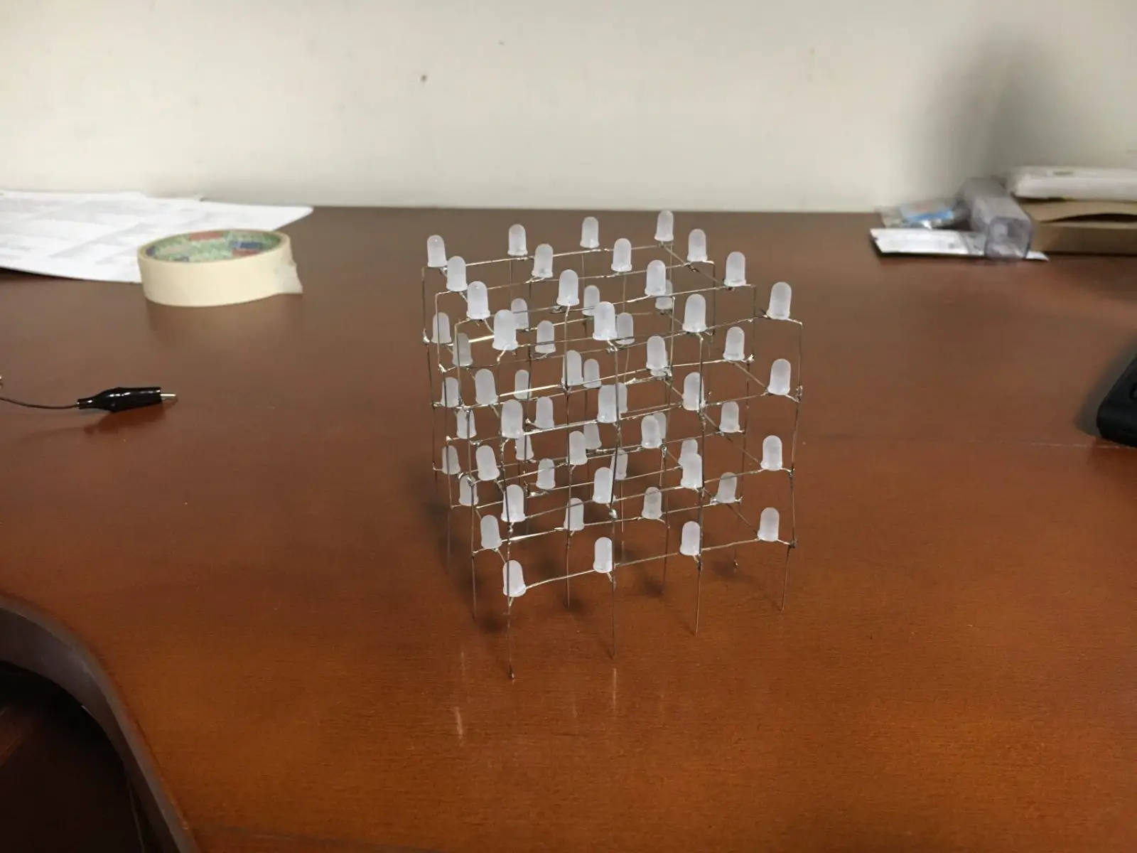
As seen in the image below, the cube is made up of an X-Y axis and 4 layers stacked on top of each other. The bottom layer is number 0 and the top one is number 3. Similarly, the LEDs are numbered like a 3-dimensional matrix. So, the bottom left LED is (1,1) on layer 0. The one above it is also (1,1) but on layer 1. The one to the right of this corner LED is (2,1) on layer 0 and so on. All the horizontal layers are the positive pins of the LEDs soldered together.
All the negative pins of the LEDs are treated as columns of this matrix cube. So we have 4 layers and 16 columns that make it 20 wires connected to the Arduino. The positive pins (layers) have 100 Ohm resistors to limit the current flow to 20mA (the standard current for an LED).
Working
The microcontroller – in our case an Arduino Uno – has current sourcing limitation on its output pins i.e. it can only deliver a safe amount of current before damage occurs. In the Arduino Uno’s case, it is 40mA. So you must be wondering, wait a minute, if an LED takes 20mA, how come we can turn on all the lights at the same time and still not burn the Arduino board? This is because at any given time, only a single LED is on.
The human eye (due to persistence of vision) cannot see quick flickering of an LED if it is switched on and off very fast. Since the code on the Arduino runs very fast, our eyes think of multiple LEDs as on. This also limits the current to safe levels as at any given time only one LED is on and even if we take the average current in 1 second, it is far below the danger threshold. For example, you want to turn on the LED at the bottom left of the cube, you will provide a positive signal from the microcontroller to its layer i.e. layer 0, this will put a positive voltage on the LEDs positive pin. Then you have to instruct the microcontroller to ground the relevant column pin of that LED, this will connect the negative pin of the LED to ground and you have a complete forward biased circuit that will light up the LED.
List of Components:
- Cardboard or wood (about 1 inch thick)
- 3V Button Cell
- Sandpaper (medium grade)
- 64 x Blue Light Emitting Diodes (LEDs)
- 4 x 100 Ohm Resistors
- 24 x Male-Male Coloured Ribbon Wires
- 1 x Female Pin Socket/Header (should have 20 pin sockets inline)
- PCB Perfboard (about 24×10 cm)
- Arduino Uno + USB Cable
- Arduino Uno power socket adapter
- 9V Batter adapter
- 9V Battery
- Zip-tie (25 cm)
- Glue Gun + Glue Stick
- Soldering Iron + Soldering Wire + Wet Foam
- Desoldering Pump (incase soldering is bad)
- Magnifying glass (to see your soldering)
- Mini Wire Cutter
- Mini Nose Plier
- Connection wire for under PCB wiring (about 1m) and sticky tape
How to Build
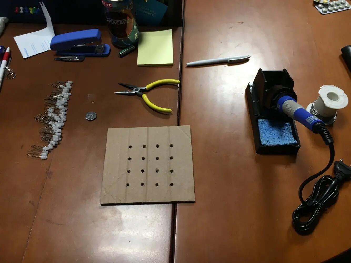
First of all, you will need a moderately thick cardboard or wood (about an inch will do). Drill holes into it so that it forms a 4×4 cube pattern with equal distances between all holes.
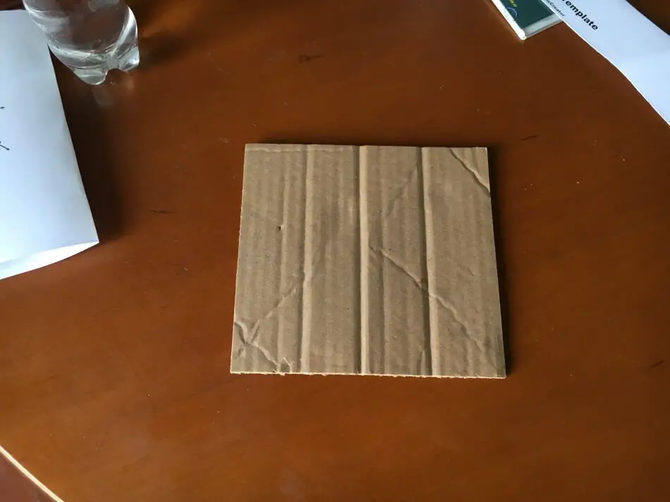
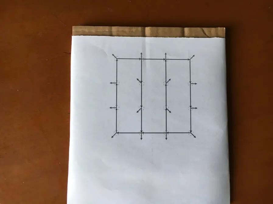
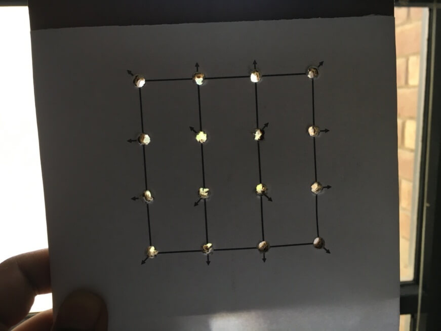
In this case, a printed pattern was placed on top of the cardboard and 5mm holes (each hole is 2.4cm from the next one (centre-centre) were drilled for the LEDs. In the picture below, you can see arrows that point to the direction of LED legs; we will look at this later.
Now, you have to test and prepare your LEDs. You can use a 3V button cell for this purpose. Test all the LEDs so that you avoid any trouble later!
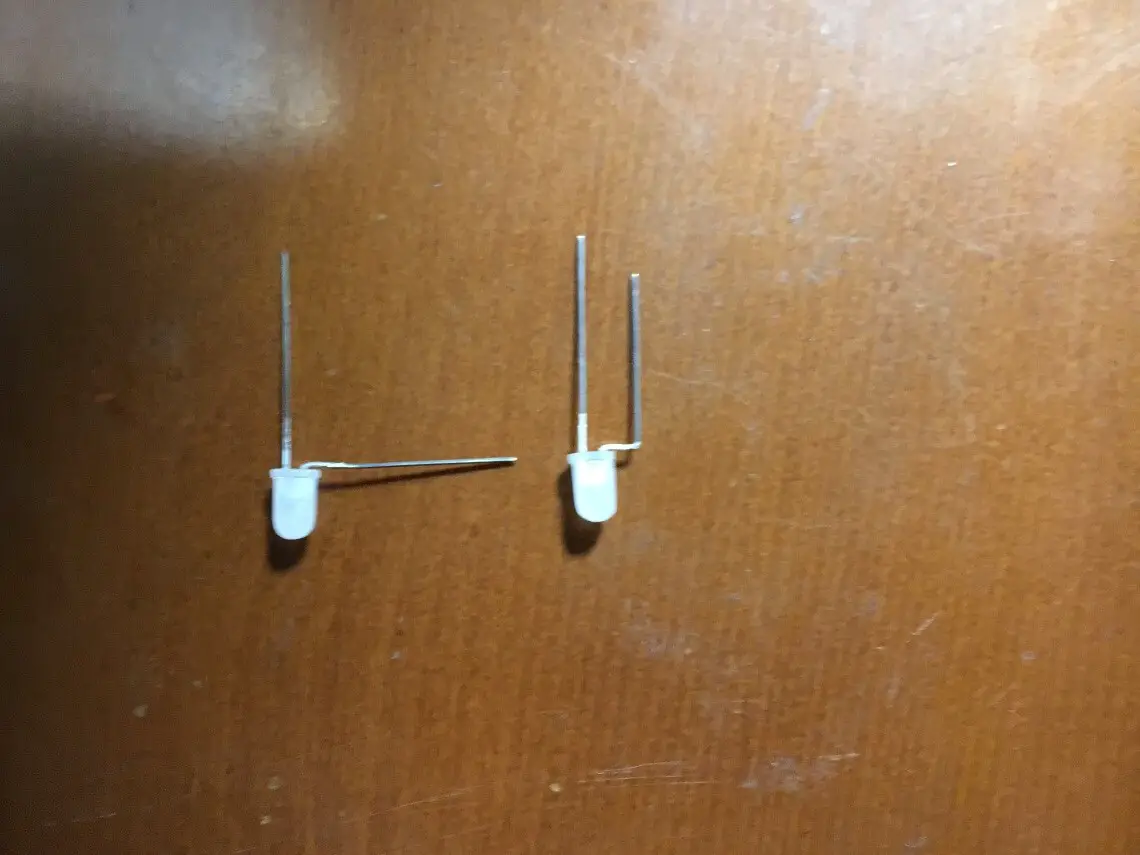
If you want light coming out of all sides of the LED, you may diffuse them by rubbing their plastic shell with sandpaper.
In the image below, the LED on the left is diffused and the one on the right is in its original transparent form. Check the difference!
Get your stuff ready for soldering. Line up the LED army and get ready for some bending and soldering.
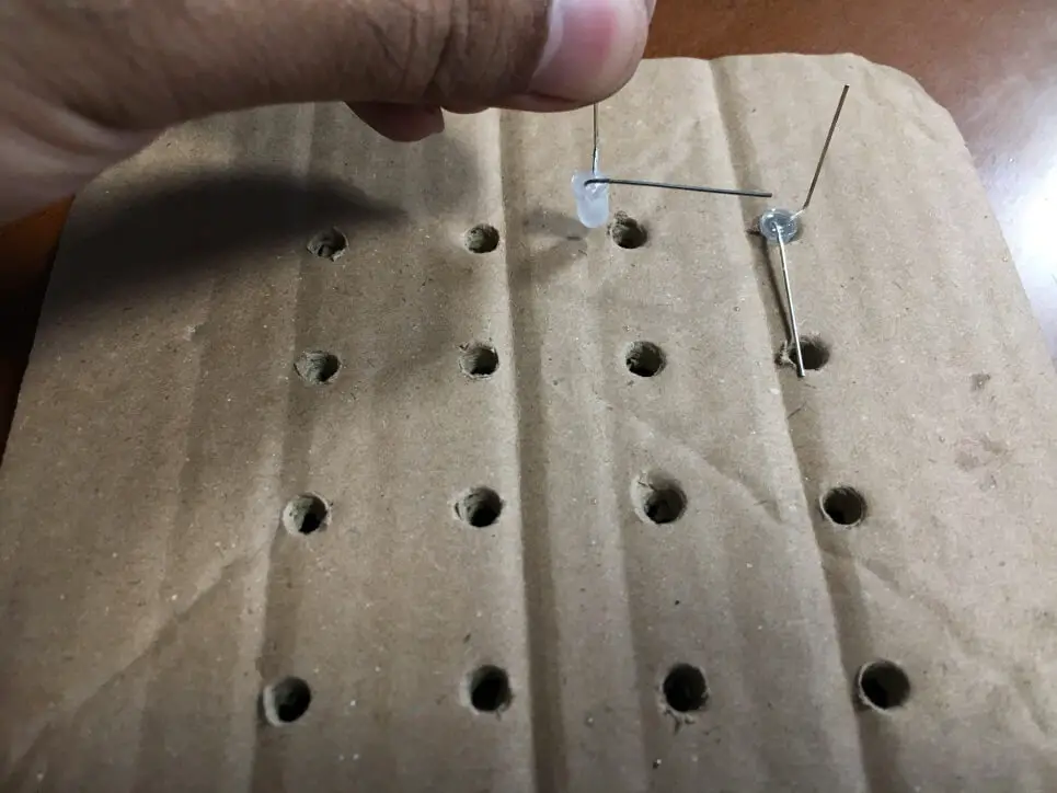
Remember, that the short leg of an LED is its Cathode (-ive pin) and the long leg is Anode (+ive pin). If you are not sure, then you can test it with a multimeter or a button cell to find the polarity. Now, using nose pliers bend the cathode (short leg) at 90o angle to the right and then again bend it upwards to make the shape as shown in the image below.
Place the LEDs in the cardboard but be careful about their orientation. Remember the arrows in an image above? The negative pins of the LEDs that are bent have to be aligned as the arrows. This is because we will be making four such layers and it is easy to solder them together. Bend all the positive legs of all LEDs and do it such that they connect all the positive terminals of the LEDs together, this will make your positive layer.
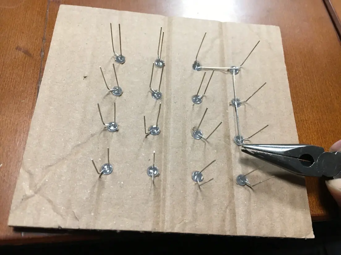
However, you will see that the two areas in the middle of this layer are left un-connected as shown by the red circle. You can connect these pins with any solid wire cut from the LEDs.
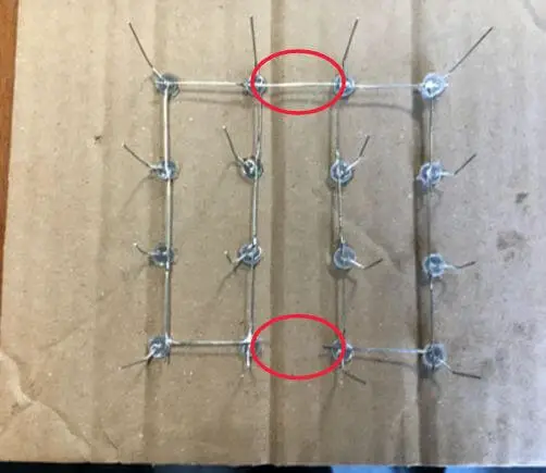
Now, using a button cell, make a simple tester to check that all the LEDs work. Hook up the positive wire to any place on the layer and one by one check all the columns with the negative wire.
First layer is complete.
Now cut all the extra pieces so that it is neat and tidy like the image below:
After making four layers, you should get ready for the mega soldering job!
In this project, simple cardboard pieces were cut and placed between the layers to be soldered. This makes it easy to solder them but you can always use other tools such as PCB holders etc.
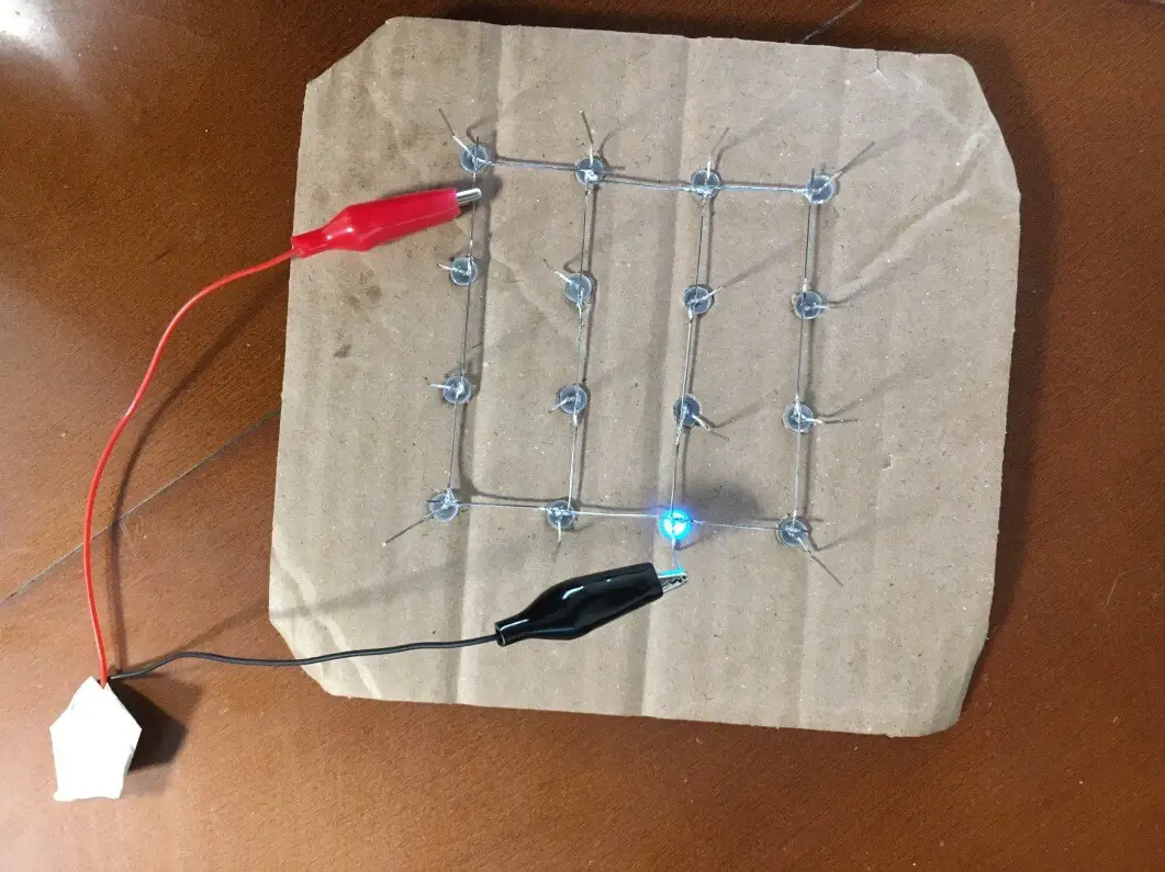
After soldering three layers, it’s a good idea to check all the LEDs once again just in case. As before, connect the positive pin of your button cell tester to the layer and then negative pin to all the LED columns (-ive pins) one by one.
Looks like we found a bugger! Just cut the faulty LED’s legs as short as you can and replace it with another one, but be careful about the bending and lengths of both pins so that it adjusts in the cube while maintaining integrity of the structure as well.
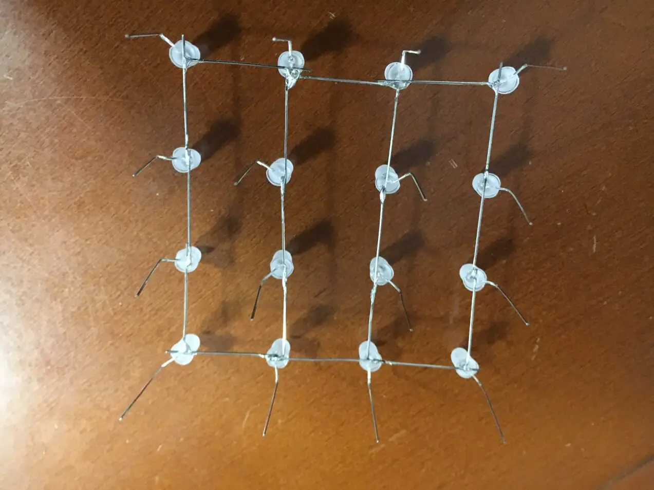
Finally, the LED cube is soldered and this is how it should look like:
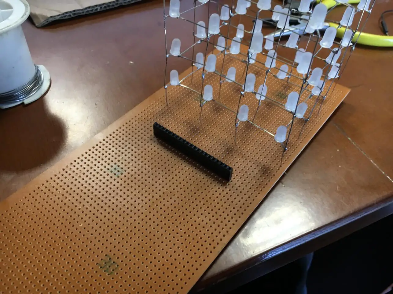
Solder a 20 pin (or more) inline female header (0.1 inch gap between pins) onto a readymade perfboard PCB and place the Cube on it (column pins). You may temporarily bend some legs of the LED cube under the board so that it doesn’t fall off but don’t solder them yet. They will be soldered with the wires coming from the female header pins later.
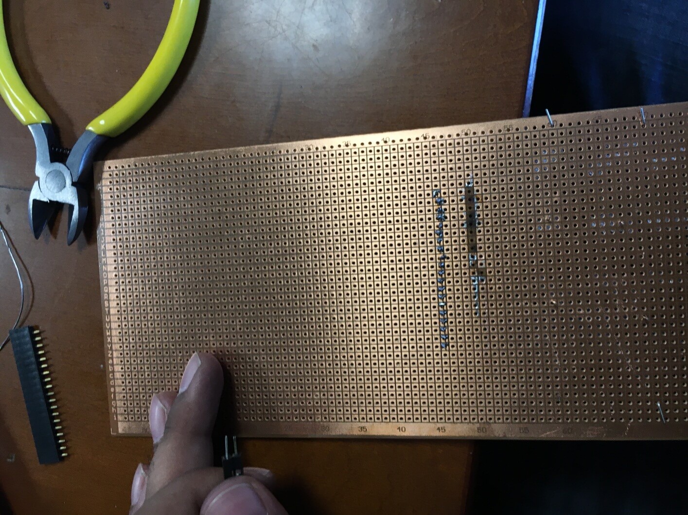
I burned some soldering points on the board, because the soldering iron was too hot and it detached the copper from the board, it also ruined the soldering for the female header.
Solder the resistors with one leg connected to the female header pins and another to be connected to every separate layer on the cube. Remember to look at the connection setup. In this project the leftmost side is pin number 0 on the Arduino all the way up till pin number 13 and then four Analog pins for the layers and then two Analog pins for the remaining columns. Do some quick testing via the female header socket as well.
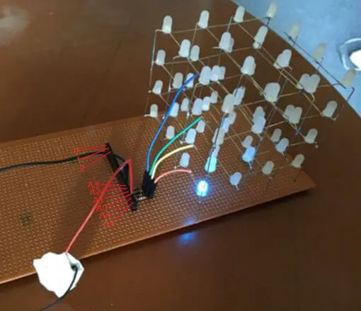
Connect all the wirings using ribbon jumper cables (male-male) according to the connections table shown below. The Arduino can be held onto the board with a zip-tie so that it can be easily removed for use in other projects. You can power the Arduino with a 9V battery and Arduino power plug (after installing the code onto the board).
For Columns:
| Coordinate (X,Y) | Pin Number on Arduino |
| 1,1 | 13 |
| 1,2 | 12 |
| 1,3 | 11 |
| 1,4 | 10 |
| 2,1 | 9 |
| 2,2 | 8 |
| 2,3 | 7 |
| 2,4 | 6 |
| 3,1 | 5 |
| 3,2 | 4 |
| 3,3 | 3 |
| 3,4 | 2 |
| 4,1 | 1 |
| 4,2 | 0 |
| 4,3 | A5 |
| 4,4 | A6 |
For Layers:
| Layer Number | Pin Number on Arduino |
| 0 | A0 |
| 1 | A1 |
| 2 | A2 |
| 3 | A3 |
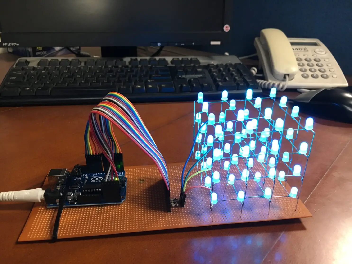
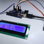
Finally, hardware is done. This is how your project may look like:
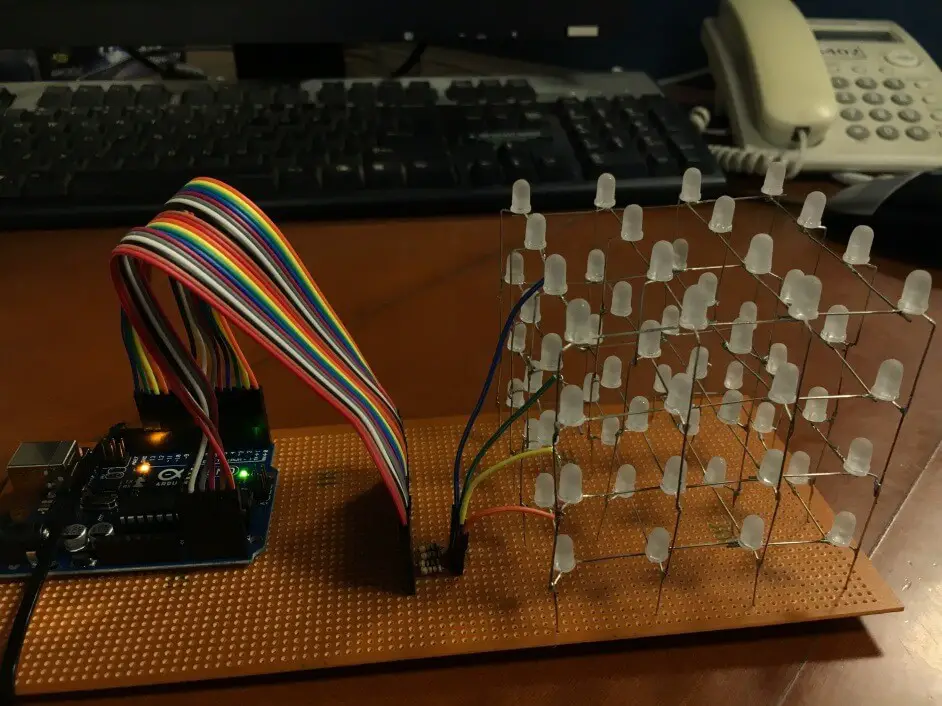
After uploading the code onto the Arduino Uno, your 4x4x4 LED Cube is ready!
You might also like:
- Arduino hx711 tutorial
- Arduino magnetic switch
- Best Arduino Kits
- gifts for engineering students
- gifts for engineers
- mpu6050 Arduino projects
- Current sensor Arduino
- Soil Moisture Sensor With Arduino
- Arduino Count up Timer Using the Nokia 5110 LCD
- Arduino Yun: Integrating or Juxtaposing Arduino with Linux
- Arduino Projects: Line Follower Robot
- Arduino RFID Project for Beginners
- Arduino MOSFET Project
- Which Arduino Should You Buy
- What Can You Do With Arduino Boards?
- Great Alternatives to the Arduino Microcontroller
- Arduino Projects: Color Sensor
- Arduino IDE Alternatives
- Arduino Mega vs. Uno
- Arduino Projects: Arduino LCD Display
- Read Arduino Rotary Encoders
- A Selection of the Best Arduino Simulators
- Arduino Projects: IR Receiver
- Arduino Light Sensor Project
- Arduino Projects: Arduino Decibel Meter
- Arduino Stopwatch Project
- Arduino Bluetooth RC Car Project
- Arduino Temperature Logger Project
- Arduino Projects: Arduino 7 Segment Display
- Arduino Projects: Clap ON Clap OFF Light
- Arduino Relay Project
- How to install Arduino Library
- Rain Sensor Arduino Project With Buzzer
- Arduino Projects: RGB LED Arduino
- Arduino Stepper Motor Project
- Arduino Projects: Arduino DC Motor Control
- Best Arduino robot kit
- Arduino 3D Printed Case
- Arduino Projects: Asynchronous LEDs Blink
- Arduino Projects: Ultrasonic Distance Sensor
- Arduino Projects: LED – 4X4X4 LED Cube
- Arduino Car Projects: Build an Obstacle Avoiding Robot With Less Than $30
- Arduino Projects: Servo Potentiometer Control
- Arduino LED Project: Knight Rider
- Arduino Projects: PIR Motion Sensor
- The Difference between Arduino and Raspberry Pi
- Top 9 Books Every Engineer Should Read
- Arduino Sensor List
- First Hand on the Arduino Uno Board
Related posts:
 Arduino Projects: Building an Arduino Countdown Timer
 The Best Arduino Starter Kits
 Arduino Projects: Ultrasonic Distance Sensor
 How to Install a Library Onto the Arduino IDE
 Arduino Projects: Building a Mini Arduino Shield With KiCAD – Part 1
 Arduino Barometer Project Using BMP180
 The Top Alternative IDE for Arduino You Should Start Using Today
 Arduino RFID Project for Beginners