If you’re familiar with Arduino, you’re likely aware of the frequent need to incorporate motors into projects, especially those involving robotics. In a previous tutorial, we discussed using a transistor to control small motors. But what if you find yourself needing to control a larger motor? The solution to this requirement lies in using a MOSFET. As defined by Wikipedia:
A type of field-effect transistor (FET). It has an insulated gate, whose voltage determines the conductivity of the device. This ability to change conductivity with the amount of applied voltage can be used for amplifying or switching electronic signals.
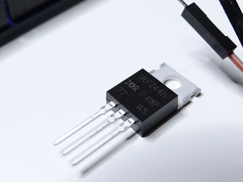
Put simply, a MOSFET is a specific type of transistor that employs a Gate rather than a Base (contrary to the bipolar transistor). Notably, the Gate in a MOSFET is isolated, rendering it considerably safer for use with Arduino. While there is more to the intricacies of MOSFETs, we won’t delve into those details in this session. For our purposes, we’ll be working with the IRF44N MOSFET, a highly economical and widely used field-effect transistor.
Arduino Mosfet
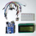
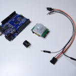
Here is the list of parts we will need for this project:
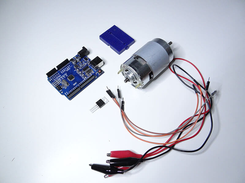
- 1 x Arduino Uno board
- 1 x IRF44N MOSFET
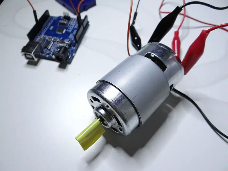
- 1 x 775 motor (or other)
- 1 x Breadboard
- 1 x jumper wires
- 1 x 12V power supply
You can use any other transistor, check out its pinout and datasheet to ensure that it can be used with the rating needed for this project.
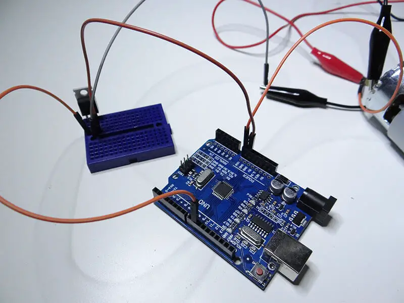
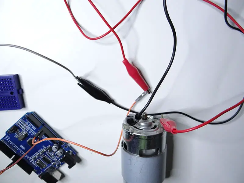
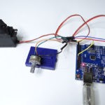
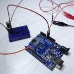
If you have all of the components that we need, you can connect them using the schematic below.
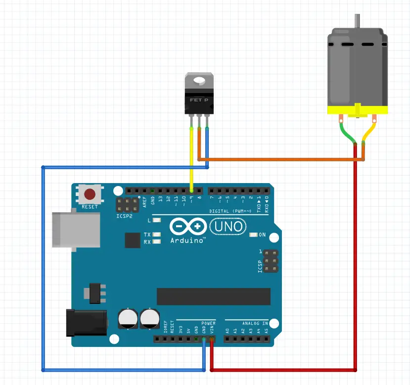
To power this circuit, we need an external power supply of 12V, but a 9V should be ok as well. You can connect it to Arduino with the DC jack.
It is very useful to use cables with crocodile clips to connect jumpers to the motor; they will hold safely and help you avoid soldering.
We can use the analogWrite function to control the motor speed with a PWN signal.
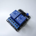
If you use a relay to control your motor, you will not be able to control it with the PWM signal. Relay responses will be too slow for such applications.
The code will increase the motor speed, slow it down, and do that over and over again. Here is the code:
As you can hear, when it is not moving, it makes odd sounds. That’s because of the current that flows through the motor coils.
And here we go! Don’t hesitate to comment below if you need further information about this project.
Feel free to check other projects here.
You might also like:
- Arduino hx711 tutorial
- Arduino magnetic switch
- Best Arduino Kits
- gifts for engineering students
- gifts for engineers
- mpu6050 Arduino projects
- Current sensor Arduino
- Soil Moisture Sensor With Arduino
- Arduino Count up Timer Using the Nokia 5110 LCD
- Arduino Yun: Integrating or Juxtaposing Arduino with Linux
- Arduino Projects: Line Follower Robot
- Arduino RFID Projects
- Which Arduino Should You Buy
- What Can You Do With Arduino Boards?
- Great Alternatives to the Arduino Microcontroller
- Arduino Projects: Color Sensor
- Arduino IDE Alternatives
- Arduino Mega vs. Uno
- Arduino Projects: Arduino LCD Display
- Read Arduino Rotary Encoders
- A Selection of the Best Arduino Simulators
- Arduino Projects: IR Receiver
- Arduino Light Sensor Project
- Arduino Projects: Arduino Decibel Meter
- Arduino Stopwatch Project
- Arduino Bluetooth RC Car Project
- Arduino Temperature Logger Project
- Arduino Projects: Arduino 7 Segment Display
- Arduino Projects: Clap ON Clap OFF Light
- Arduino Relay Project
- Install a Library Onto the Arduino IDE
- Arduino Projects: Rainfall Detector
- Arduino Projects: RGB LED Arduino
- Arduino Stepper Motor Project
- Arduino Projects: Arduino DC Motor Control
- The Top Affordable Arduino Robot Kit
- Arduino 3D Printed Case
- Arduino Projects: Asynchronous LEDs Blink
- Arduino Projects: Ultrasonic Distance Sensor
- Arduino Projects: LED – 4X4X4 LED Cube
- Arduino Car Projects: Build an Obstacle Avoiding Robot With Less Than $30
- Arduino Projects: Servo Potentiometer Control
- Arduino LED Project: Knight Rider
- Arduino Projects: PIR Motion Sensor
- The Difference between Arduino and Raspberry Pi
- Top 9 Books Every Engineer Should Read
- Top Used Sensors for Arduino
- First Hand on the Arduino Uno Board
Related posts:
 Arduino Projects: Building an Arduino Countdown Timer
 Arduino Projects: LED – 4X4X4 LED Cube
 Arduino Projects: PIR Motion Sensor
 The Best Arduino Starter Kits
 Arduino Relay Project
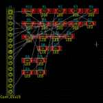 Arduino Projects: Building a Mini Arduino Shield With KiCAD – Part 1
 The Top Alternative IDE for Arduino You Should Start Using Today
 Arduino RFID Project for Beginners
Fritzing pictorials ARE NOT schematics! A pet peeve on the maker community is that misunderstanding.
Too many of my electrical engineering students see articles like this, which are otherwise helpful, but leave thinking they know what a real schematic looks like. The pictorial may me ok for a novice with a simple circuit but it fails with larger more complete ones.
Btw you did not label the fet pins. Gate to pwm, source to griund, drain to motor (load).
We thought schematic might be too complex for beginners. So we decided to use Fritzing pictorials which turn out to work like a charm. I am still looking for a name that could describe it better than “schematics”
Thanks Mark!
No problem. The term though is ‘pictorial’ for what Fritzing produces…