The AZ-Delivery 2.4” TFT LCD Touch Display boasts 320x 240 pixels with 16-bit color. It has Touch capabilities, a built-in SD card drive, and plugs straight onto the top of an Arduino UNO or Mega. Amazon charges less than £11 for this device. It offers a major step up from the tiny SSD1306 128×64 monochrome display.

The TFT screen is much larger than the SSD1306 128×64 and much more colourful. The package includes an SD card reader on the underside and a stylus for accurate touch-screen control.
AZ-Delivery usually supply an e-book (pdf document for download) with their boards. The German version comes first followed by other languages. This has just become available and provides setup instructions and a demonstration graphics only sketch.
The underside of the board has labels on the pins. As the board is an Arduino shield, it will only fit on a UNO in one position. The SD card reader sits between USB and the power socket. It will also plug into and Arduino MEGA 2560. J1 and J2 fit into the digital pins, covering D0 to D13, while J3 and J4 fit into the analog and power pins.
LCD_D0 to LCD_D7 provide an 8-bit bus with the other LCD pins on J3.
The card reader uses the SPI pins, D11, D12, and D13 with chip select on D10. (Not D4 as used in all the Arduino example sketches.)
This picture shows the underside of the board with an SD card inserted in the card reader.
I searched the Web for drivers and examples and found much praise for the TFT graphics, reports of problems with the Touch control, and nothing about the SD card reader on this board.
In the end, I installed several libraries (with all dependencies): Adafruit GFX, Adafruit TFT LCD, Adafruit TouchScreen, Adafruit ILI9341, MCUFRIEND_kbv, and SPFD5408-master. (The last 2 are not essential but include some interesting examples). The SD library is included in the basic Arduino set.
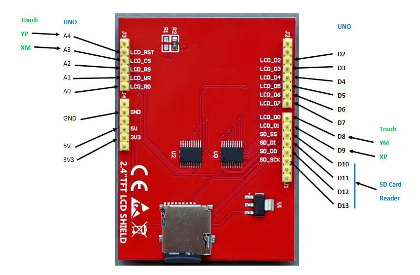
I’ve used GFX with mono displays such as SSD1306 and soon got the TFT display working. The following script gives some idea about what it can do. I’ve included pixels, text (of varying sizes), lines, rectangles, triangles, squares, graphs, screen rotation, and text on a path. I was very impressed with the clarity, speed, brightness, and colors produced.
Here is my first graphics sketch:
//  AZ-Delivery 2.4" TFT LCD touch shield Demo
//          Shield on Arduino UNO
//  +++ Tony Goodhew 17th September 2020 +++
//  Tutorial45.com

// Essential Adafruit GFX Libraries
#include <Adafruit_GFX.h>
#include <Adafruit_TFTLCD.h>

#define LCD_CS A3     // Chip Select goes to Analog 3
#define LCD_CD A2     // Command/Data goes to Analog 2
#define LCD_WR A1     // LCD Write goes to Analog 1
#define LCD_RD A0     // LCD Read goes to Analog 0
#define LCD_RESET A4  // Can alternately just connect to Arduino's reset pin

// Colour definitions for 64k colour mode
// Bits 0..4 ->   Blue 0..4
// Bits 5..10 ->  Green 0..5
// Bits 11..15 -> Red 0..4
#define BLACK 0x0000
#define WHITE 0xFFFF
#define GREY 0x7BEF
#define LT_GREY 0xC618
#define GREEN 0x07E0
#define LIME 0x87E0
#define BLUE 0x001F
#define RED 0xF800
#define AQUA 0x5D1C
#define YELLOW 0xFFE0
#define MAGENTA 0xF81F
#define CYAN 0x07FF
#define DK_CYAN 0x03EF
#define ORANGE 0xFCA0
#define PINK 0xF97F
#define BROWN 0x8200
#define VIOLET 0x9199
#define SILVER 0xA510
#define GOLD 0xA508
#define NAVY 0x000F
#define MAROON 0x7800
#define PURPLE 0x780F
#define OLIVE 0x7BE0
// Put colours in an array for random colour access
int tftColours[] = {GREY,LT_GREY,GREEN,LIME,BLUE,RED,AQUA,YELLOW,MAGENTA,CYAN,DK_CYAN,
                   ORANGE,PINK,BROWN,VIOLET,SILVER,GOLD,NAVY,MAROON,PURPLE,OLIVE, WHITE};

// Create the TFT object using all pin assignments
Adafruit_TFTLCD tft(LCD_CS, LCD_CD, LCD_WR, LCD_RD, LCD_RESET);

// =========== SETUP ================
void setup() {
  Serial.begin(9600); // Useful for debugging
  tft.reset();
  tft.begin(0x9341);  // SDFP5408
  tft.setRotation(3); // 320 wide by 240 high - reset button on left
  tft.fillScreen(BLACK);
  tft.setCursor(30, 50);
  tft.setTextColor(RED);
  tft.setTextSize(3);
  tft.println("AZ-Delivery");
  tft.setTextColor(YELLOW);
  tft.setCursor(30, 90);
  tft.println("2.4 TFT LCD");
  tft.setCursor(30, 120);
  tft.println("Touch Display");
  tft.setCursor(30, 150);
  tft.println("& SD Drive");
  tft.setCursor(30, 200);
  tft.setTextColor(RED);
  tft.setTextSize(2);
  tft.println("Tutorial45.com");
  delay(4000);
  tft.fillScreen(BLACK); // Clears the screen

  // Display some Pixels
  for (int m = 0; m <= 4000; m++)  {     // 4000 random pixels
    int xx = random(320);
    int yy = random(240);
    tft.drawPixel(xx, yy, tftColours[random(22)]);
  }
  delay(2000);
  tft.fillScreen(BLACK);

  int x = 1;
  int y = 50;
  int h = 50;
  int w = 50;
  int xj = 160;
  int yj = 170;
  int t = RED;

  // Quilt
  for (int xx=0; xx < 320; xx = xx + 32){
    for (int yy = 0; yy < 240; yy = yy + 24){
      tft.fillRect(xx,yy,32,24,tftColours[random(22)]);
    }
  }

  delay(2000);
  tft.fillScreen(BLACK);
  // Grid
  tft.fillScreen(BLACK);
  for (int x =0; x < 320; x=x +10) {
    tft.drawFastVLine(x+5, 0, 240, RED);
  }
  for (int y = 0; y < 240; y = y + 10) {
    tft.drawFastHLine(0, y+3, 320 , BLUE);
  }
  delay(2000);
  tft.fillScreen(BLACK);
  for (int x = 60; x < 200; x=x +25) {
    int yy = x-10;
    tft.drawRect(x,yy,40,45,tftColours[random(22)]);
    //drawRect( x,  y,  w,  h, c)
  }
  delay(2000);
  // Rectangles
  tft.fillScreen(BLACK);
  for (int x = 60; x < 200; x=x +25) {
    int yy = x-10;
    tft.fillRect(x,yy,40,45,tftColours[random(22)]);
    //fillRect( x,  y,  w,  h, c)
  }
  delay(2000);
  tft.fillScreen(BLACK);
  int r = 5;
  for (int x = 60; x < 200; x=x +25) {
    int yy = x-10;
    tft.drawRoundRect(x,yy,40,45,r,tftColours[random(22)]);
    r = r + 3;
    //drawRoundRect( x,  y,  w,  h, r, c)
  }
  delay(2000);
  tft.fillScreen(BLACK);
  r = 5;
  for (int x = 60; x < 200; x=x +25) {
    int yy = x-10;
    tft.fillRoundRect(x,yy,40,45,r,tftColours[random(22)]);
    //fillRoundRect( x,  y,  w,  h, r, c)
    r = r + 3;
  }
  delay(2000);
  // A few circles
  tft.fillScreen(BLACK);
  for (int r = 120;r > 5; r=r-10){
    tft.fillCircle(80, 40, r, tftColours[random(22)]);
    delay(50);
  }
  for (int r = 5;r <120; r=r+10){
    tft.fillCircle(random(200), random(120), r, tftColours[random(22)]);
    delay(50);
  }
  delay(2000);
  tft.fillScreen(BLACK);
  for (int r = 120;r > 5; r=r-10){
    tft.drawCircle(80 + random(60), 40 + random(70), r, tftColours[random(22)]);
  }
  delay(1000);
  for (int r = 5;r <120; r=r+10){
    tft.drawCircle(random(200), random(120), r, tftColours[random(22)]);
  }
  delay(2000);

  // Draw Sine and Cosine curves
  float sine[300];
  float cosine[300];
  tft.fillScreen(BLACK);
  tft.setTextColor(YELLOW);
  tft.setCursor(10,220);
  tft.setTextSize(2);
  tft.println("Sine Curve");
  tft.setTextColor(RED);
  tft.setCursor(125,20);
  tft.println("Cosine Curve");
  tft.drawFastHLine(9, 120, 300 ,BLUE);
  for (int i = 0; i < 300; i++){
    sine[i] = (sin(radians(i *1.2))) * -1;
    tft.drawPixel(i+9,int(sine[i]*100+120),YELLOW);
    cosine[i] = (cos(radians(i *1.2))) * -1;
    tft.drawPixel(i+9,int(cosine[i]*100+120),RED);
  }
  delay(2000);
  // Screen rotation - 4 0ptions 0, 90 180 and 270 degrees
  tft.fillScreen(BLACK);
  tft.setCursor(25,32);   // Title splash
  tft.print("Rotate Screen");
  delay(1000);
  tft.fillScreen(BLACK);
  for (int rt = 0; rt <= 3  ; rt++){
    tft.setRotation(rt % 4);               // Values 0..3
    tft.fillScreen(BLACK);
    int cw = WHITE;
    tft.fillTriangle(0,0,0,30,30,0,cw);     // (x,y,x1,y1,x2,y2,colour)
    tft.fillTriangle(0,15,40,50,15,0,cw);
    tft.fillTriangle(15,0,50,40,0,15,cw);
    tft.fillTriangle(40,50,50,40,20,20,cw);
    tft.setTextSize(2);                     // Middle size
    tft.setTextColor(BLACK);
    tft.setCursor(5,5);
    tft.println(rt % 4);
    tft.setTextColor(RED);
    tft.setCursor(50,50);
    tft.setTextSize(3);
    tft.println("TFT LCD");
    delay(1000);
  }
  tft.setRotation(3);
  tft.fillScreen(BLACK);
  // Text Sizes

  tft.setTextSize(1);                // Normal 1:1 pixel scale
  tft.setTextColor(WHITE);           // Draw white text
  tft.setCursor(0,0);                // Start at top-left corner
  tft.println("Text Sizes\n");
  tft.setTextSize(2);                // Medium
  tft.println("AZ-Delivery\n");
  tft.setTextSize(3);                // Large - rather blocky
  tft.println("TFT LCD 320x240\n");
  tft.setTextSize(4);                // Larger - very blocky
  tft.println("Touch\n");
  tft.setTextSize(5);                // Largest - very blocky
  tft.println("2.4 inch");
  tft.setTextSize(1);
  tft.setTextColor(BLUE);
  tft.setCursor(220,220);
  tft.println("Tutorial45.com");
  delay(2000);

  // Text along a path
  tft.fillScreen(BLACK);
  char msg2[] = "+ TFT LCD+Arduino=MAGIC +";
  for (int n = 0; n < 25; n++){
    char ch = msg2[n];
    int p = n*12; // was 9
    float y1 = (cos(radians(p *2.8125)) * -1);
    int yy = int(y1 *25.0 + 100);
    tft.drawChar(p + 5, yy, ch, RED, BLACK, 2);
  }
  delay(4000);
  tft.fillScreen(BLACK);
  char msg[] =  "+++ Tutorial45.com +++";
  tft.fillScreen(BLACK);
  for (int n = 0; n < 22; n++){
    char ch = msg[n];
    int p = n*9;
    float y1 = (sin(radians(p *2.8125)) * -1);
    int yy = int(y1 *25.0 + 100);
    tft.drawChar(p + 60, yy, ch, GREEN, BLACK, 1);
  }
  tft.setTextSize(1);
  tft.setTextColor(BLUE);
  tft.setCursor(220,120);
  tft.println("Finished");
}

// ------------ LOOP NOT NEEDED --------------------

void loop() {}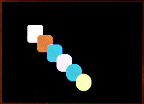
Color picking
Normally, when setting the color of an RGB LED, you have a range of 0-255 (0-FF hex) for each RGB component, which gives white = F, red = FF000, green FF00, and blue = FF. This is a 24-bit color and takes 3 bytes. 224 gives 16,777,216 different colors. The TFT screen is a 16-bit color device that can display 65,536 colors – more than enough. Here, the range is limited to 5 bits each for red and blue and 6 for green. (Our eyes are more sensitive to green, so It gets the extra bit of accuracy.)
| R4 | R3 | R2 | R1 | R0 | G5 | G4 | G3 | G2 | G1 | G0 | B4 | B3 | B2 | B1 | B0 |
To convert a 24-bit colour to a 16-bit colour held in integers r, g and b, each with range 0 – 255.
// Convert 24-bit colours to 16-bit colours
// Tony Goodhew 22 Sept 2020
// Tutorial45.com
void setup() {
  Serial.begin(9600);
  int r = 255;
  int g = 255;
  int b = 255;
  unsigned int n = r/8 * 2048 + g/4 * 32 + b/8;
  Serial.println(n,HEX);
}
void loop() {}
The following sketch indicates the colors available by converting an array of 24-bit color values into their 16-bit equivalent and displaying them on the screen with the data. There are not enough pixels on the screen to display all the colors simultaneously, so the last part of the sketch takes out the least significant green bit and displays half the available colors in six ways.
//  Almost all the colours - several ways
//  AZ-Delivery 2.4" TFT LCD touch shield Demo
//          Shield on Arduino UNO
//  +++ Tony Goodhew 25th September 2020 +++
//  Tutorial45.com

#include <Adafruit_GFX.h>
#include <Adafruit_TFTLCD.h>

#define LCD_CS A3     // Chip Select goes to Analog 3
#define LCD_CD A2     // Command/Data goes to Analog 2
#define LCD_WR A1     // LCD Write goes to Analog 1
#define LCD_RD A0     // LCD Read goes to Analog 0
#define LCD_RESET A4  // Can alternately just connect to Arduino's reset pin

#define RED 0xF800
#define YELLOW 0xFFE0
#define BLUE 0x001F
// Create the TFT object with all pin assignments
Adafruit_TFTLCD tft(LCD_CS, LCD_CD, LCD_WR, LCD_RD, LCD_RESET);

// =========== SETUP ================
int title(String s){
    tft.fillScreen(0); // Clears the screen
    tft.setTextSize(3);
    tft.setCursor(60, 200);
    tft.setTextColor(0xC618); // Lt_Grey
    tft.println("32768 pixels");
    tft.setCursor(120, 5);
    tft.println(s);
  }
void setup() {
  Serial.begin(9600); // Useful for debugging
  tft.reset();
  tft.begin(0x9341);  // SDFP5408 - start the display
  tft.setRotation(3); // 320 wide by 240 high - reset button on left
  tft.fillScreen(0); // Clears the screen
  tft.setCursor(30, 50);
  tft.setTextColor(RED);
  tft.setTextSize(3);
  tft.println("AZ-Delivery");
  tft.setTextColor(YELLOW);
  tft.setCursor(30, 90);
  tft.println("16-bit colours");
  tft.setCursor(30, 120);
  tft.println("from");
  tft.setCursor(30, 150);
  tft.println("24-bit colours");
  tft.setTextColor(BLUE);
  tft.setCursor(30, 185);
  tft.setTextSize(2);
  tft.println("Tutorial45.com");
  delay(4000);
  // A few interesting 24-bit colours - some dim - some bright!
  unsigned long c1[] = {
        0x000000,0xFFFFFF,0x333333,0x666666,0x999999,0xCCCCCC,0xCCCC99,0x9999CC,0x666699,
        0x660000,0x663300,0x996633,0x003300,0x003333,0x003399,0x000066,0x330066,0x660066,
        0x990000,0x993300,0xCC9900,0x006600,0x336666,0x0033FF,0x000099,0x660099,0x990066,
        0xCC0000,0xCC3300,0xFFCC00,0x009900,0x006666,0x0066FF,0x0000CC,0x663399,0xCC0099,
        0xFF0000,0xFF3300,0xFFFF00,0x00CC00,0x009999,0x0099FF,0x0000FF,0x9900CC,0xFF0099,
        0xCC3333,0xFF6600,0xFFFF33,0x00FF00,0x00CCCC,0x00CCFF,0x3366FF,0x9933FF,0xFF00FF,
        0xFF6666,0xFF6633,0xFFFF66,0x66FF66,0x66CCCC,0x00FFFF,0x3399FF,0x9966FF,0xFF66FF,
        0xFF9999,0xFF9966,0xFFFF99,0x99FF99,0x66FFCC,0x99FFFF,0x66CCFF,0x9999FF,0xFF99FF,
        0xFFCCCC,0xFFCC99,0xFFFFCC,0xCCFFCC,0x99FFCC,0xCCFFFF,0x99CCFF,0xCCCCFF,0xFFCCFF};
  unsigned int c2[80];

  int l = 81;
  tft.fillScreen(0); // Clears the screen
  for (int i = 0; i < l; i++){
    int r = c1[i] >> 16;              // Get red 24-bit component - 0 to 255
    int g = (c1[i] & 0x00ff00) >> 8;  // Get green
    int b = (c1[i] & 0x0000ff);       // Get blue
    unsigned long col2 = r/8 * 2048 + g/4 * 32 + b/8;  // Create 16-bit value
    // int division removes least significant bits
    // multiplication shifts bits left
    tft.fillScreen(0);
    tft.fillRect(40,20,240,120,col2);
    tft.setTextSize(3);
    tft.setCursor(37, 145);
    tft.setTextColor(0xC618); // Lt_Grey
    tft.print("24-bit: ");
    tft.println(c1[i] & 0xFFFFFF,HEX);
    tft.println(" RGB: "+String(r) +" "+ String(g) +" "+String(b));
    int col3 = col2 & 0xFFFF;
    c2[i] = col3;
    String q =String(c2[i], HEX);
    q.toUpperCase();
//    String s = String("   16-bit: "+String(c2[i], HEX));
    String s = String("   16-bit: "+q);
    tft.println(s);
    delay(800);
  }
  int x = 0;
  int y = 0;
  unsigned int c = 0;
  String s = "R G B";
  title(s);
  for (int r = 0; r <32; r = r + 1){
    for (int g = 0; g < 64; g=g+2){
      for (int b = 0; b < 32; b = b + 1){
        unsigned int c = r * 2048 + g * 32 + b;  // Create 16-bit value
        tft.drawPixel(x +30, y+45, c);
        x = x + 1;
          if (x > 255){
            x = 0;
            y = y + 1; } } } }
  delay(1000);
  s = "B G R";
  title(s);
  x = 0; y = 0;
  for (int b = 0; b <32; b = b + 1){
    for (int g = 0; g < 64; g = g + 2){
      for (int r = 0; r < 32; r = r + 1){
        unsigned int c = r * 2048 + g * 32 + b;  // Create 16-bit value
        tft.drawPixel(x +30, y+45, c);
        x = x + 1;
          if (x > 255){
            x = 0;
            y = y + 1; } } } }
  delay(1000);
  s = "G B R";
  title(s);
  x = 0; y = 0;
  for (int g = 0; g < 64; g = g + 2){
    for (int b = 0; b <32; b = b + 1){
      for (int r = 0; r < 32; r = r + 1){
        unsigned int c = r * 2048 + g * 32 + b;  // Create 16-bit value
        tft.drawPixel(x +30, y+45, c);
        x = x + 1;
          if (x > 255){
            x = 0;
            y = y + 1; } } } }
  delay(1000);
  s = "R B G";
  title(s);
  x = 0; y = 0;
  for (int r = 0; r < 32; r = r + 1){
    for (int b = 0; b <32; b = b + 1){
      for (int g = 0; g < 64; g = g + 2){
        unsigned int c = r * 2048 + g * 32 + b;  // Create 16-bit value
        tft.drawPixel(x +30, y+45, c);
        x = x + 1;
          if (x > 255){
            x = 0;
            y = y + 1; } } } }
  delay(1000);
  s = "B R G";
  title(s);
  x = 0; y = 0;
  for (int b = 0; b <32; b = b + 1){
     for (int r = 0; r < 32; r = r + 1){
        for (int g = 0; g < 64; g = g + 2){
        unsigned int c = r * 2048 + g * 32 + b;  // Create 16-bit value
        tft.drawPixel(x +30, y+45, c);
        x = x + 1;
          if (x > 255){
            x = 0;
            y = y + 1; } } } }
  delay(1000);
  s = "G R B";
  title(s);
  x = 0; y = 0;
  for (int g = 0; g < 64; g = g + 2){
    for (int r = 0; r < 32; r = r + 1){
      for (int b = 0; b <32; b = b + 1){
        unsigned int c = r * 2048 + g * 32 + b;  // Create 16-bit value
        tft.drawPixel(x +30, y+45, c);
        x = x + 1;
          if (x > 255){
            x = 0;
            y = y + 1; } } } }
}
void loop() {} //-- LOOP NOT NEEDED --
Using the SD card reader
Looking at the bottom of the board there are 4 pins used for communication with the SD card reader:
SD_SS pin 10-SS = Chip Select
SD_DI pin 11- MOSI
SD_DO pin 12-MISO
SD_SCK pin 13-CLOCK
This is a standard SD card reader and uses the SPI pins on the UNO and pin 10 as the Chip Select.
The Arduino.cc site lists the following SPI pins on their different boards
| Arduino / Genuino Board | MOSI | MISO | SCK | SS (slave) | SS (master) | Level |
| Uno or Duemilanove | 11 or ICSP-4 | 12 or ICSP-1 | 13 or ICSP-3 | 10 | – | 5V |
| Mega1280 or Mega2560 | 51 or ICSP-4 | 50 or ICSP-1 | 52 or ICSP-3 | 53 | – | 5V |
| Leonardo | ICSP-4 | ICSP-1 | ICSP-3 | – | – | 5V |
If you need to use the SD card with a MEGA you will need to run the board via jumper leads.
The SD card reader library is included with the basic setup, so we do not need to load a fresh library. The examples cover the simple tasks of creating, writing to, reading from and deleting files at a very basic level, all with strings.
I used a 16GB SD-HC class 4 card. It is easy to insert into the reader with a gentle push. Push in again to extract if necessary.
To check that everything is in order you can run the “CardInfo” sketch from the Examples tab of the File muenu. (File =>> Examples =>> SD =>> CardInfo.) Make sure you set:
const int chipSelect = 10;
on the line before the setup routine. I got the following with my card, which I had been using earlier.

At this point it is worth running the other example sketches to get a feel for how the card reader works.
You may have noticed that:
- This is a very basic serial file device.
- You can only have one file open at a time.
- You write strings to the file (so numbers have to be converted to strings before they are saved.)
- You can make up a record of several strings which are in turn made up of characters.
- You concatenate the sub-strings to make the record string using a comma as a delimiter.
- Each line in the file is a record which terminates with “\n”.
- If you write to an existing file the new data is appended at the end.
- In the examples the chip select pin is 4. We have to use pin 10 when the shield is plugged into an UNO.
An obvious use for the SD reader is to log readings from sensors and display the results on the TFT display. Unfortunately, the shield covers and uses most of the pins. The solution is to connect just the SD reader and power pins with jump leads which leaves plenty of pins to collect data from sensors.
Most Arduino users seldom use string manipulation. The documentation and a few simple examples of how to use strings are well scattered over the Web and difficult to find. The first sketch demonstrates how to create a file of 5 records/lines, each made up from an integer, a string, and a floating-point variable. The file is called datalog6.txt.
// Create a log file sketch
// Write demo log file: 'datalog6.txt' with 3 fields per
//      record: Int, String and Float
// The SD_Read_File sketch can process it.
// Tony Goodhew 21 Sept 2020
// SD reader on TFT shield – Output to Serial Monitor
// Tutorial45.com
#include <SPI.h>
#include <SD.h>
const int chipSelect = 10;
void setup() {
  // Open serial communications and wait for port to open:
  Serial.begin(9600);{}
  Serial.print("Initializing SD card...");
// see if the card is present and can be initialized:
  if (!SD.begin(chipSelect)) {
    Serial.println("Card failed, or not present");
    // Halt
    while (1);
  }
  Serial.println("card initialized.");
  File dataFile = SD.open("datalog6.txt", FILE_WRITE);
  // Set up test data in 3 arrays
  int i[] = {1, 2222, 3, -4, 5};
  String s[] = {"Tony", "Fred", "Anne", "Mags", "William"};
  float f[] = {3.14, 2.2, 3.3333, 10.66, -5.5};
  String j = "";  // record string
  Serial.println("Writing datalog6.txt");
  // Loop for 5 data records
  for (int p=0; p < 5; p++){
    // Pack the data up into a string, j
    // Build long string with 3 data items as strings
    //    separated with commas
    j = String(i[p]) + "," + s[p]+ "," + String(f[p]); // One record
    // Display the long string
    Serial.println(j);
    // Save j to SD Card
    // if the file is available, write to it:
    if (dataFile) {
      dataFile.println(j);  // Write j to the file
    }
    // if the file isn't open, pop up an error:
    else {
    Serial.println("error opening datalog6.txt");
    }
  }
  dataFile.close();
  Serial.println("\nFile datalog6.txt written - FINISHED!\n");
}
void loop() {}
The second sketch reads the data we have saved in the datalog6.txt file. It splits each line/record into the 3 strings and then converts one to an Integer and the another to Floating Point. Just to prove that they are now stored as numbers it multiplies them together and displays the result.
// Read the data back from a log file: 'datalog6.txt'
// Tony Goodhew 21 Sept 2020
// SD reader on TFT shield
// Tutorial45.com

#include <SPI.h>
#include <SD.h>

const int chipSelect = 10;

void setup() {
  // Open serial communications and wait for port to open:
  Serial.begin(9600);
  while (!Serial) {
    ; // wait for serial port to connect. Needed for native USB port only
  }
  Serial.print("Initializing SD card...");

  // see if the card is present and can be initialized:
  if (!SD.begin(chipSelect)) {
    Serial.println("Card failed, or not present");
    // don't do anything more:
    while (1);
  }
  Serial.println("card initialized.");

  // Open the file
  File dataFile = SD.open("datalog6.txt");
  Serial.println("Reading datalog6.txt");
  String j = ""; // Holds a line from the data file (3 fields = 1 record)

  if (dataFile) {
    while (dataFile.available()) {        // Not reached the End Of File
      j = dataFile.readStringUntil('\n'); // Get single line from file
      Serial.println("\n"+j);
      int comma1 = j.indexOf(',');
      int comma2 = j.indexOf(',', comma1 + 1);
      Serial.println("Commas: " + String(comma1) + " "+ String(comma2));
      // Separate back into 3 strings at the commas
      String ii = j.substring(0,comma1);              // integer
      String sname = j.substring(comma1 +1, comma2);  // string
      String ff = j.substring(comma2 +1);             // float
      // Print out the strings
      Serial.println(ii);
      Serial.println(sname);
      Serial.println(ff);
      int iOut = ii.toInt(); // Convert back to integer
      float fOut = ff.toFloat();  // Convert back to Floating Point
      float res = iOut * fOut;    // Calculation with both numbers
      Serial.println(sname +": " + String(res)+"\n");  // Output the result
    }
    dataFile.close();
  }
  // if the file isn't open, print up an error message
  else {
    Serial.println("error opening datalog6.txt");
  }
}
void loop() {}
Using the Touch Layer
This is the part that often causes the most trouble with many owners giving up at this point. It may be because there are several different configurations of the pins used to connect to the touch layers of the screen on the many varied breakout boards and shields using this display. In this case four of the pins are used, at different times, to control both the graphics or the touch elements of the screen.
How does a touch screen sense position?
This is a resistive touch screen, rather than a capacitive one. Above the graphics, layers are two transparent resistive layers held apart by tiny dimples. One is connected at the top and bottom and the other at the sides. A potential difference is applied across them and when the stylus or a finger presses on the screen an electrical connection is made between the resistive layers.
The Analog pins are used to measure the voltages at that point on the two resistive layers, one at a time, in the same manner as we read the voltage from the wiper of a potentiometer – a potential divider. Using these values, it is possible to calculate, quite accurately, the coordinates of the point on the screen where the pressure has been applied. Calibration is often needed to improve accuracy. Adafruit suggests reading the resistance across the X plate (XP = D8 and XM = A2). On my board, I got 341 Ohms. Use this value as SENSITIVITY.
// Simple Drawing Script for AZ-Delivery TFT Touch 240x320 Shield
// Tony Goodhew 30 Sept 2020
// Modified from Adafruit examples for a similar shield
// Tutorial45.com
// Adafruit GFX Libraries
#include <Adafruit_GFX.h>
#include <Adafruit_TFTLCD.h>
#include <TouchScreen.h>

#define LCD_CS A3     // Chip Select goes to Analog 3
#define LCD_CD A2     // Command/Data goes to Analog 2
#define LCD_WR A1     // LCD Write goes to Analog 1
#define LCD_RD A0     // LCD Read goes to Analog 0
#define LCD_RESET A4  // Can alternately just connect to Arduino's reset pin

// 16-bit colour values:
#define BLACK 0x0000
#define BLUE 0x001F
#define RED 0xF800
#define GREEN 0x07E0
#define CYAN 0x07FF
#define MAGENTA 0xF81F
#define YELLOW 0xFFE0
#define WHITE 0xFFFF
unsigned int c[] = {BLACK,RED,GREEN,BLUE,CYAN,MAGENTA,YELLOW,WHITE};
int cc = c[1];

// Create the TFT (Graphics) object - named pins
Adafruit_TFTLCD tft(LCD_CS, LCD_CD, LCD_WR, LCD_RD, LCD_RESET);

// Set up the touch screen element of the TFT screen
#define YP A3  // must be an analog pin, use "An" notation!
#define XM A2  // must be an analog pin, use "An" notation!
#define YM 9   // can be a digital pin
#define XP 8   // can be a digital pin
#define SENSITIVITY 341                   // Was 300 = Resistance A2 to D8
#define MINPRESSURE 10
#define MAXPRESSURE 1000
#define TS_MINX  150
#define TS_MINY  120
#define TS_MAXX  920
#define TS_MAXY  940
#define MINPRESSURE 10
#define MAXPRESSURE 1000
// Create Touch Screen object
TouchScreen ts = TouchScreen(XP, YP, XM, YM, SENSITIVITY);

void palette(){       // Create colour 'buttons' at top of screen
   int w = 30;
   int h = 40;
   tft.fillRect(0, 0, w, h, BLACK);
   tft.fillRect(w, 0, w, h, RED);
   tft.fillRect(w*2, 0, w, h, GREEN);
   tft.fillRect(w*3, 0, w, h, BLUE);
   tft.fillRect(w*4, 0, w, h, CYAN);
   tft.fillRect(w*5, 0, w, h, MAGENTA);
   tft.fillRect(w*6, 0, w, h, YELLOW);
   tft.fillRect(w*7, 0, w, h, WHITE);
}
//---------SETUP--------------------
void setup() {
  Serial.begin(9600);
  tft.reset();
  tft.begin(0x9341);  // SDFP5408
  tft.fillRect(0,0, 240,320, BLACK);  // Drawing area
  palette();  // Drawing colour buttons
}
//---------Main Loop------------
void loop(){
  TSPoint p = ts.getPoint(); // Read the Touch Screen
  // Shared pins - fix direction
  pinMode(XM, OUTPUT);
  pinMode(YP, OUTPUT);

  // Check for pressure on screen
  if (p.z > MINPRESSURE && p.z < MAXPRESSURE) {
/*  // Debugging
    Serial.print("X = "); Serial.print(p.x);
    Serial.print("\tY = "); Serial.print(p.y);
    Serial.print("\tPressure = "); Serial.println(p.z);
*/
    // Scale Touch values to fit TFT screen
    // Adjust final number to get drawn dot under the stylus point (fudge factors!)
    p.x = map(p.x, TS_MINX, TS_MAXX, tft.width(), 0) -10;
    p.y = map(p.y, TS_MINY, TS_MAXY, tft.height(), 0)-14;

/*  // Debugging
    Serial.print("("); Serial.print(p.x);
    Serial.print(", "); Serial.print(p.y);
    Serial.println(")");
*/
    if (p.y < 40){                              // In the palette area?
      if (p.x <30){                             // Black to clear drawing area
        tft.fillRect(0, 40, 240,299, BLACK);}
      else{                                     // Change colour
        cc = c[p.x / 30];
      }
    }
    else{
      tft.fillCircle(p.x, p.y, 2, cc);         // Draw dot at stylus point
    }
  }
}
Try running the sketch to draw on the screen. The BLACK palette ‘button’ clears the screen and the others change the ‘ink’ colour. If the dot drawn is not directly under the stylus you can adjust the ‘fudge factors’ in the scaling section.
16-bit Colour Mixing Project
As a final example here is a sketch which shows off the Touch screen with buttons, bar graphs and colours. The buttons allow the user to adjust the RGB mix to display all the possible colours available. If you find one you particularly like it displays the hex value of the 16-bit colour.
Gently pressing on the buttons at the bottom with the stylus changes the RGB values within their allowed ranges. The bars move to show the fraction of maximum possible for each of the red, green and blue values.

// Project Sketch for AZ-Delivery TFT Touch 240x320 Shield
// Tony Goodhew 2 October 2020
// Tutorial45.com
// Adafruit GFX Libraries
#include <Adafruit_GFX.h>
#include <Adafruit_TFTLCD.h>
#include <TouchScreen.h>

#define LCD_CS A3     // Chip Select goes to Analog 3
#define LCD_CD A2     // Command/Data goes to Analog 2
#define LCD_WR A1     // LCD Write goes to Analog 1
#define LCD_RD A0     // LCD Read goes to Analog 0
#define LCD_RESET A4  // Can alternately just connect to Arduino's reset pin

// 16-bit colour values:
#define BLACK 0x0000
#define BLUE 0x001F
#define RED 0xF800
#define GREEN 0x07E0
#define WHITE 0xFFFF

// Create the TFT (Graphics) object - named pins
Adafruit_TFTLCD tft(LCD_CS, LCD_CD, LCD_WR, LCD_RD, LCD_RESET);

// Set up the touch screen element of the TFT screen
#define YP A3  // must be an analog pin, use "An" notation!
#define XM A2  // must be an analog pin, use "An" notation!
#define YM 9   // can be a digital pin
#define XP 8   // can be a digital pin
#define SENSITIVITY 341                   // Was 300 = Resistance A2 to D8
#define MINPRESSURE 10
#define MAXPRESSURE 1000
#define TS_MINX  150
#define TS_MINY  120
#define TS_MAXX  920
#define TS_MAXY  940
#define MINPRESSURE 10
#define MAXPRESSURE 1000
// Create Touch Screen object
TouchScreen ts = TouchScreen(XP, YP, XM, YM, SENSITIVITY);

int left[] ={5,45,85,125,165,205};    // left edge of buttons
int right[]={35,75,115,155,195,235};  // right edge of buttons
int red = 15;  // Colours set at mid-points
int green = 31;
int blue = 15;
int old_r = 0;
int old_g = 0;
int old_b = 0;

void graph(int xx, int yy, int p, unsigned int col){
  // Draw a bar graph
  tft.fillRect(xx, yy, 200, 20, BLACK);  // Overwrite to background colour
  tft.fillRect(xx, yy, p * 2, 20, col);  // New bar graph
}

void palette(){
  // Create 'buttons' near bottom of screen
  int w = 30;
  int h = 30;
  int y = 280;
  for (int i=0; i<6;i++){
    unsigned int bc = GREEN;
    if (i < 2){bc = RED;}
    if (i > 3){bc = BLUE;}
    tft.fillRect(5 + i *(w+10), y, w, h, bc);
  }
  tft.setTextColor(WHITE);
  tft.setTextSize(3);
  for (int i=0; i<6; i = i + 2){
    tft.setCursor(12 + i *(w+10), y +4);
    tft.println("+");}
  for (int i=1; i<6; i = i + 2){
      tft.setCursor(12 + i *(w+10), y +4);
      tft.println("-");}
}
void show(){
  // Display values and bar graphs
  unsigned int n = red * 2048 + green * 32 + blue;
  tft.fillRect(0, 0, 240, 60, n);
  tft.drawFastVLine(19, 95, 90, 0x7BEF); // Graph axis
  tft.drawFastVLine(18, 95, 90, 0x7BEF);
  tft.setTextSize(3);
  tft.setTextColor(WHITE);
  if (n > 0xF2BF){tft.setTextColor(BLACK);}  // Black on bright colours
  tft.setCursor(85,20);
  tft.println(n,HEX);
  tft.fillRect(0, 230, 240, 46, BLACK);
  String rS = String(red);
  if (red < 10){rS = " " + rS;}  // Left alignment
  tft.setTextColor(WHITE);
  tft.setCursor(25,230);
  tft.println(rS);
  String gS = String(green);
  if (green < 10){gS = " " + gS;}
  tft.setCursor(105,230);
  tft.println(gS);
  String bS = String(blue);
  if (blue < 10){bS = " " + bS;}
  tft.setCursor(186,230);
  tft.println(bS);
  tft.setTextSize(2);
  int rp = red * 100 / 31;
  int gp = green * 100 / 63;
  int bp = blue * 100 / 31;
  String rz = String(rp) + "%";
  String gz = String(gp) + "%";
  String bz = String(bp) + "%";
  if (rp < 100){rz = " " + rz;}
  if (rp < 10){rz = " " + rz;}
  tft.setCursor(13,260);
  tft.println(rz);
  if (gp < 100){gz = " " + gz;}
  if (gp < 10){gz = " " + gz;}
  tft.setCursor(92,260);
  tft.println(gz);
  if (bp < 100){bz = " " + bz;}
  if (bp < 10){bz = " " + bz;}
  tft.setCursor(174,260);
  tft.println(bz);
  if (old_r != red){                // red value changed?
    graph(20,100,rp,RED);           // Update graph
    old_r = red;
    }
  if (old_g != green){              // green value changed?
    graph(20,130,gp,GREEN);
    old_g = green;
  }
  if(old_b != blue){               // blue value change
    graph(20,160,bp,BLUE);
    old_b = blue;
  }
}
//---------SETUP------------------
void setup() {
  Serial.begin(9600);
  tft.reset();
  tft.begin(0x9341);  // SDFP5408
  tft.fillRect(0,0, 240,320, BLACK);    // Drawing area
  palette();  // Drawing buttons
  show();  // Display the inital values
}
//---------Main Loop------------
void loop(){
  TSPoint p = ts.getPoint(); // Read the Touch Screen
  // Shared pins - fix direction
  pinMode(XM, OUTPUT);
  pinMode(YP, OUTPUT);

  // Check for pressure on screen
  if (p.z > MINPRESSURE && p.z < MAXPRESSURE) {

    // Scale Touch values to fit TFT screen
    // Adjust final values to improve accuracy
    p.x = map(p.x, TS_MINX, TS_MAXX, tft.width(), 0) -10;
    p.y = map(p.y, TS_MINY, TS_MAXY, tft.height(), 0)-14;

    if ((p.y >= 300) & (p.y <= 330)){               // In the button area?
      if ((p.x >= left[0]) & (p.x <= right[0])){    // Process buttons
        red = red +1;                               //   as necessary
        if (red > 31){red = 31;}
      }
      else if ((p.x >= left[1]) & (p.x <= right[1])){
        red = red -1;
        if (red < 0){red = 0;}
      }
      else if ((p.x >= left[2]) & (p.x <= right[2])){
        green = green + 1;
        if (green > 63){green = 63;}
      }
      else if ((p.x >= left[3]) & (p.x <= right[3])){
        green = green -1;
        if (green < 0){green = 0;}
      }
      else if ((p.x >= left[4]) & (p.x <= right[4])){
        blue = blue + 1;
        if (blue > 31){blue = 31;}
      }
      else if ((p.x >= left[5]) & (p.x <= right[5])){
        blue = blue - 1;
        if (blue < 0){blue = 0;}
      }
    }
    // Update Display
    show();
  }
}
Conclusion
There is a small amount of jitter as the bar graph re-draws, but overall, the shield works quickly and well. After the screen has updated and is waiting for a touch, the image is steady, sharp, and bright. Once you have calibrated the touch device, it is very accurate, as demonstrated by the small (30×30 pixel buttons), and provides excellent, colorful graphics on a usefully large display.
The SD card reader is a bonus and could always be used via jump wires to record values from sensors on the other pins. These values could then be displayed graphically with a different sketch.
I was very pleased with the display’s quality and the Touch device’s accuracy. It sits neatly and securely on a UNO or a MEGA 2560. With an SD card reader included, it was excellent value, and I will make good use of it in the future.
Related posts:
 Top 9 Books Every Engineer Should Read
 Arduino Projects: LED – 4X4X4 LED Cube
 Arduino Projects: PIR Motion Sensor
 Arduino Relay Project
 Arduino MOSFET Project
 6 Reasons to Build Your Next Arduino Project With XOD
 Best PCB Design Software for Electrical Engineers
 Learn How to Use a Multimeter Like A Pro