The Arduino IDE provides a serial monitor window which proves to be quite useful when it comes to printing values to debug a project. However, you can further enhance this functionality by attaching a small screen to your project that can provide feedback, display menus, and show results, improving its utility significantly. Moreover, this modification can also help to make your project completely portable.
I will be looking at three small and inexpensive LED screens that you can easily connect to your Arduino.
The Technology
These devices are Liquid Crystal Displays and have been around for some time. They do not emit light but block it. They may have a back-light or rely on reflected light.
Each display is made up of several layers and makes use of polarised light. If you polarise light horizontally with one filter you can cut off the light completely with a vertically polarised filter. Some liquids will twist the angle of polarisation when a voltage is applied to them allowing polarised light to pass through the filters.
They are called “twisted nematic liquid crystals”. If you sandwich such a crystal between two polarizers, crossed at 90°, the light would normally be blocked. If a voltage is applied to the crystal it ‘twists’ the light’s polarisation as it passes through the crystal and it is allowed through the second polarizing filter. A liquid crystal display is made up of many layers but remains very thin.
The one of the first uses of LCD displays was with electronic calculators in the early 1970s, replacing the previous tiny red 8 segment displays with magnifying lenses. These small monochrome devices were soon used in clocks, watches and other small, low power applications.
| Advantages | Disadvantages |
| High contrast Low cost Low power Compact and very light | Often need an additional light source Fragile Slow to react Limited temperature range – avoid freezing |
The Display Modules
I’m going to be looking at 3 different boards:
- MakerHawk 12C OLED display with 128×64 pixels (blue)
- MakerHawk 12C OLED display with 128×32 pixels (white)
- AZ-Delivery HD44780 2004 Display with I2C converter (4 rows of 20 characters)
The first two can display graphic elements (lines, circles, pictures etc and text) while the last is a character only display.
MakerHawk OLED displays with SSD1306 driver chip
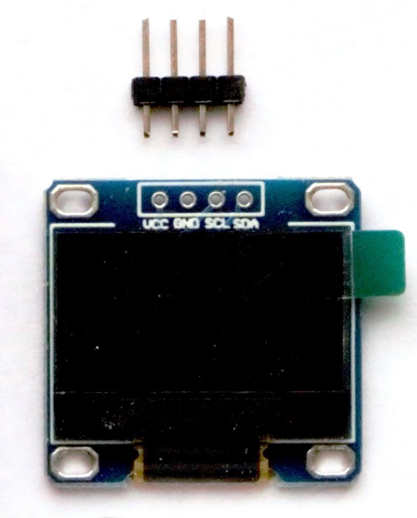
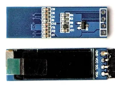
These are I2C devices and only need to be connected to 3.3V-5V, GND, SCL, and SDA. They are very small (diagonals are 0.96” and 0.91” respectively) lightweight, with tiny pixels and excellent contrast, making them very easy to read. The larger display is blue while the smaller is white.
They do not have a backlight and rely on reflection. The larger is supplied with 40 colored DuPont F-F cables and connection pins that need to be soldered to the board. You get two of the smaller displays in the packet, but no connection pins, sockets, or cables. There is no information supplied on how to connect them up to your Arduino or how to control them. The screens are protected with a plastic cover. (Take off carefully as the screens are delicate.) The four connections for I2C are clearly marked on the boards. Both devices have I2C addresses of 0x3C.
The next step is to solder on the pins or sockets and connect them up to your Arduino.
MakerHawk 12C OLED display with 128×64 (blue)
MakerHawk 12C OLED display with 128×32 pixels (white)
Project #1: Using Arduino with the LCD 128×64 pixel SSD1306 board
Materials needed:
- Arduino – standard or cloned UNO
- MakerHawk 12C OLED display with 128×64
- Connecting wires
- 10K Ohm potentiometer
For these demonstrations the potentiometer will provide a variable input voltage on the A0 pin of the Arduino.
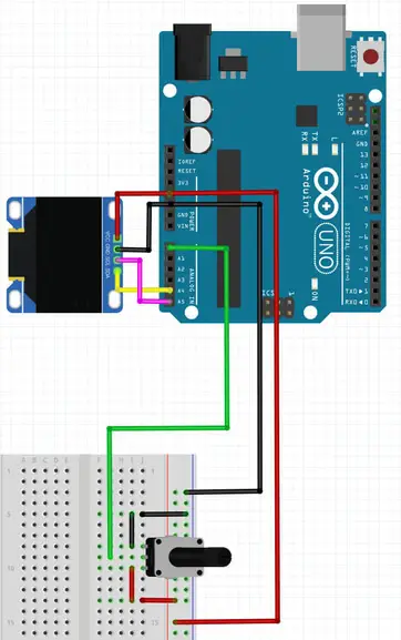
A4 is the SDA pin and A5 is the SCL pin on an Arduino UNO. Other boards may have different pins so check before you connect up. VCC goes to 5V and GND to GND. The wiper of the potentiometer goes to A0 on the Arduino and the other pins to 5V and GND.
Now we need to obtain suitable libraries for the SSD1306 boards and for the graphics routines. Adafruit has provided some very useful libraries which are easy to install on the current version of the Arduino IDE.
Start the Arduino software and use the Library Manager to search for and install the Adafruit SSD1306 library (2.2.1 at the time of writing). It covers both sizes of board and I2C and SPI versions. It also installs all the dependencies. Take the option to install the GFX library and the BusIO library at the same time. (https://github.com/adafruit/Adafruit_SSD1306)
Check at the bottom of the Examples Menu that all necessary libraries have been installed.
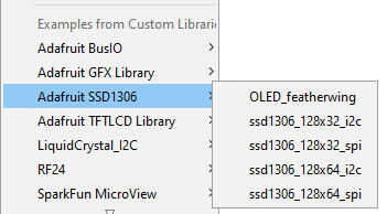
Notice that the library covers both sizes of screen as well as SPI and I2C protocols.
Now we are ready to see can see what the display can do. I’ve provided a couple of scripts to demonstrate the versatility of these displays. The first shows the graphical capabilities, without any user intervention via the potentiometer. I’ve included plenty of comments so you can see what is going on.
The screen origin is top left (0,0) with 128 horizontal pixels (0…127) moving right and 64 vertical pixels (0…63) moving down.
The screen may be small but it is very clear and sharp with enough room to be very useful.
/* SSD1306 128x64 I2C OLED display with Arduino UNO
* Illustrates text elements and graphics
* Tony Goodhew 3rd July 2020
* Tutorial45.com
*/
#include <Wire.h>
#include <Adafruit_GFX.h>
#include <Adafruit_SSD1306.h>
#define SCREEN_WIDTH 128 // OLED display width, in pixels
#define SCREEN_HEIGHT 64 // OLED display height, in pixels
// Declaration for an SSD1306 display connected to I2C (SDA, SCL pins)
#define OLED_RESET 4 // Reset pin # (or -1 if sharing Arduino reset pin)
Adafruit_SSD1306 display(SCREEN_WIDTH, SCREEN_HEIGHT, &Wire, OLED_RESET);
void show() { // Often used sequence - Function to simplify code
display.display();
delay(2000);
display.fillScreen(SSD1306_BLACK);
}
void show2() { // Faster
display.display();
delay(400);
display.fillScreen(SSD1306_BLACK);
}
void setup() {
Serial.begin(9600);
randomSeed(analogRead(0));
// SSD1306_SWITCHCAPVCC = generate display voltage from 3.3V internally
if(!display.begin(SSD1306_SWITCHCAPVCC, 0x3C)) { // Old Address 0x3D for 128x64
Serial.println(F("SSD1306 allocation failed"));
for(;;); // Don't proceed, loop forever
}
// Initialise some variables
int cw = SSD1306_WHITE; // colour white
int cb = SSD1306_BLACK; // colour black
int wait = 2000; // 2 second delay
int x0 = 7; // 3 pairs of co-ordinates
int y0 = 7;
int x1 = 123;
int y1 = 23;
int x2 = 50;
int y2 = 61;
int w = 117; // Width
int h = 56; // Height
// Draw a Title screen
display.clearDisplay();
display.setTextSize(2); // Middle
display.setTextColor(cw);
display.setCursor(0,15);
display.println("SSD1306");
display.println(" GFX");
display.setCursor(10,53);
display.setTextSize(1);
display.println("Tutorial45.com");
display.display(); delay(wait);
randomSeed(analogRead(1));
display.fillScreen(cw); // Fill screen WHITE
display.setTextColor(cb);
display.setCursor(40,53);
display.println("Tutorial45.com");
display.setTextColor(cw);
display.display(); delay(wait);
display.fillScreen(cb); // Fill screen BLACK
display.display();
// Display some Pixels
for (int m = 0; m <= 17; m++) { // 17 random pixels
int xx = random(127);
int yy = random(63);
display.drawPixel(xx, yy, cw);
display.display();
delay(130);
}
delay(wait);
display.clearDisplay();
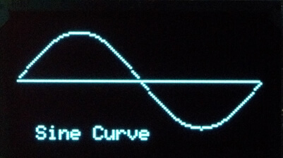
// Draw a Sine curve
float sine[127];
// Initialise variables
display.fillScreen(cb);
display.setTextColor(cw);
display.setCursor(10,56);
display.setTextSize(1);
display.println("Sine Curve");
display.drawFastHLine(0, 32, 127 ,cw);
for (int i = 0; i < 128; i++){
sine[i] = (sin(radians(i *2.8125))) * -1;
display.drawPixel(i,int(sine[i]*25+32),cw);
display.display();
}
show();
// Demonstrate basic shapes
display.drawLine(x0, y0, x1, y1 + 30, cw);
show2();
display.drawFastVLine(50, 12, h, cw); // Fast vertical line of length l
show2();
display.drawFastHLine(5, 45, w ,cw); // Fast horizontal line of length w
show2();
// Random lines
for( int m = 0; m <10; m++) {
int xr = random(127);
int yr = random(63);
int xl = random(127);
int yl = random(63);
display.drawLine(xr,yr,xl,yl,cw);
display.display();
}
show();
display.drawRect(x0, y0, w, h, cw);
show2();
display.fillRect(x0, y0, w, h, cw);
show2();
display.drawRoundRect(x0, y0, w, h, 14, cw); // Rounded corners of radius 14
show2();
display.fillRoundRect(x0, y0, w, h, 14, cw);
show2();
// Grid
for (int x =0; x < 130; x=x +10) {
display.drawFastVLine(x, 0, 64, cw);
display.display();
}
for (int y = 0; y < 64; y = y + 10) {
display.drawFastHLine(0, y, 127 ,cw);
display.display();
}
show();
// A few circles
for (int r = 5;r <32; r=r+5){
display.drawCircle(63, 31, r, cw);
display.display();
delay(500);
}
display.fillCircle(63, 31, 31, cw);
show();
display.drawTriangle(x0, y0, x1, y1, x2, y2, cw);
show();
display.fillTriangle(x0, y0, x1, y1, x2, y2, cw);
show();
// Screen rotation - 4 0ptions 0, 90 180 and 270 degrees
display.clearDisplay();
display.setCursor(25,32); // Title splash
display.print("Rotate Screen");
display.display(); delay(wait);
for (int rt = 0; rt <= 4; rt++){
display.setRotation(rt % 4); // Values 0..3
display.clearDisplay();
display.fillTriangle(0,0,0,30,30,0,cw); // (x,y,x1,y1,x2,y2,colour)
display.fillTriangle(0,15,40,50,15,0,cw);
display.fillTriangle(15,0,50,40,0,15,cw);
display.fillTriangle(40,50,50,40,20,20,cw);
display.setTextSize(2); // Middle size
display.setTextColor(cb);
display.setCursor(5,5);
display.println(rt % 4);
display.display(); delay(wait);
}
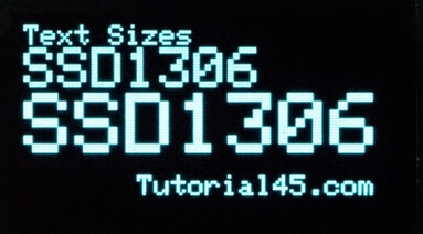
// Text Sizes
display.clearDisplay();
display.setTextSize(1); // Normal 1:1 pixel scale
display.setTextColor(cw); // Draw white text
display.setCursor(0,0); // Start at top-left corner
display.println("Text Sizes");
display.setTextSize(2); // Medium
display.println("SSD1306");
display.setTextSize(3); // Large - rather blocky
display.println("SSD1306");
display.setTextSize(1);
display.setCursor(40,53);
display.println("Tutorial45.com");
show();
display.clearDisplay();
// Text along a path
char msg[] = "+++ Tutorial45.com +++";
display.clearDisplay();
for (int n = 0; n < 21; n++){
char ch = msg[n];
int p = n*6;
float y1 = (sin(radians(p *2.8125)) * -1);
int yy = int(y1 *25.0 + 32);
display.drawChar(p, yy, ch, cw, cb, 1);
display.display();
}
show();
display.clearDisplay();
char msg2[] = "SSD1306+Arduino=MAGIC";
for (int n = 0; n < 21; n++){
char ch = msg2[n];
int p = n*6;
float y1 = (cos(radians(p *2.8125)) * -1);
int yy = int(y1 *25.0 + 32);
display.drawChar(p, yy, ch, cw, cb, 1);
display.display();
}
show();
display.clearDisplay();
char Msg[] = ".+Arduino+.";
y2 = 50;
for (int n = 0; n < 11; n++){
char ch = Msg[n];
int xx = n*12;
display.drawChar(xx, y2, ch, cw, cb, 2); // (x,y,Char,foreGnd,backGnd,size)
y2 = y2 - 5; // Moving up the screen
display.display();
}
show();
// Finish up
display.setTextSize(1); // Normal 1:1 pixel scale
display.setTextColor(cw);
display.setCursor(0,25);
display.setTextSize(2);
display.println("Finished");
display.setCursor(40,53);
display.setTextSize(1);
display.println("Tutorial45.com");
display.display();
}
void loop() {
// Empty - Linear program which halts
}The most important thing to remember is that none of the changes specified by the script will actually appear on the screen until the instruction display.display() is executed. The changes go on in the background and this instruction forces updates to the display. In this script it is often hidden inside the show() routine.
The documentation for the library is found here: https://cdn-learn.adafruit.com/downloads/pdf/adafruit-gfx-graphics-library.pdf
Remember that these are simple monochrome displays so we only have two colours.
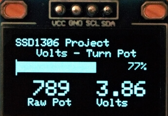
The second example demonstrates the user updating the display by changing the physical input. As the potentiometer is twisted some of the values displayed change and the bar graph changes in length.
/* SSD1306 128x64 I2C OLED display, Arduino UNO and 10K Ohm pot on A0
 * Tony Goodhew  3rd July 2020
 * Tutorial45.com
 */

#include <Wire.h>
#include <Adafruit_GFX.h>
#include <Adafruit_SSD1306.h>

#define SCREEN_WIDTH 128 // OLED display width, in pixels
#define SCREEN_HEIGHT 64 // OLED display height, in pixels

// Declaration for an SSD1306 display connected to I2C (SDA, SCL pins)
#define OLED_RESET     4 // Reset pin # (or -1 if sharing Arduino reset pin)
Adafruit_SSD1306 display(SCREEN_WIDTH, SCREEN_HEIGHT, &Wire, OLED_RESET);

int sensorPin = A0;   // select the input pin for the potentiometer
int sensorValue = 0;  // variable to store the value coming from the sensor

void setup() {
  Serial.begin(9600);
  // SSD1306_SWITCHCAPVCC = generate display voltage from 3.3V internally
  if(!display.begin(SSD1306_SWITCHCAPVCC, 0x3C)) { // Address 0x3D for 128x64
    Serial.println(F("SSD1306 allocation failed"));
    for(;;); // Don't proceed, loop forever
  }
  display.clearDisplay();
  display.setTextSize(1);             // Small
  display.setTextColor(SSD1306_WHITE);
  display.setCursor(0,0);             // Top Left corner
  display.println("SSD1306 Project");
  display.setCursor(20,10);
  display.println("Volts - Turn Pot");
  display.setCursor(64,118);
  display.setCursor(0,57);
  display.println("  Raw Pot    Volts");
  display.display();
}
// Functions for right alignment of integers
int iAlign2(int s){  // Space in 100s and 10s
  if (s < 100) {display.print(" ");}
    if (s < 10) {display.print(" ");}
}
int iAlign3(int s){  // Space in 1000s
  if (s < 1000) {display.print(" ");}
  iAlign2(s);
}
int bar(int yy,int v) {
  display.drawLine(0,yy,0,yy+14, SSD1306_WHITE);
  display.fillRect(1,yy+2,127,10,SSD1306_BLACK);
  display.fillRect(0,yy+2,v,10, SSD1306_WHITE);
  display.setCursor(102,yy+2);
  iAlign2(v);
  display.print(v);
  display.println("%");
  display.display();
}
// ++++++++++++Main Loop ++++++++++++++
void loop() {
  // Read pot and display values
  sensorValue = analogRead(sensorPin); // Read the value from the sensor
  float volts = (sensorValue * 5.0 / 1023.0);  // Calculate voltage
  int x = float(sensorValue * 100.0/1018);     // Calculate percentage
  bar(20,x);  // Redraw bar graph
  display.fillRect(0, 40, 127, 15, SSD1306_BLACK); // Clear line
  display.setCursor(5,40);
  display.setTextSize(2);
  iAlign3(sensorValue);
  display.println(sensorValue);  // Raw pot value
  display.setCursor(78,40);
  display.print(volts);          // Equivalent voltage
  display.setTextSize(1);
}
Notice that the whole screen is not updated. The top two lines and the bottom line are written in the setup() section. In the loop we update the bar graph and the 3 values. Flicker is minimal and caused by the ADC rather than the screen. The Raw Pot value has been right aligned by add spaces with the functions.
Project #2 Using the Arduino with the LCD SSD1306 128×32 pixel board
I’m now going to look at the smaller board. Obviously, it has half the screen size of the previous board, but this may have advantages if you only want to display a small amount of information or fit the display into a very confined space.
The connections are the same as on the previous display and properly labeled so just swap over the displays. This is a digital voltmeter using the potentiometer as input.
/* SSD1306 128x32 I2C OLED display, Arduino UNO and 10K Ohm pot on A0
 * Tony Goodhew  3rd July 2020
 * Tutorial45.com
 */

#include <Wire.h>
#include <Adafruit_GFX.h>
#include <Adafruit_SSD1306.h>

#define SCREEN_WIDTH 128 // OLED display width, in pixels
#define SCREEN_HEIGHT 32 // OLED display height, in pixels

// Declaration for an SSD1306 display connected to I2C (SDA, SCL pins)
#define OLED_RESET     4 // Reset pin # (or -1 if sharing Arduino reset pin)
Adafruit_SSD1306 display(SCREEN_WIDTH, SCREEN_HEIGHT, &Wire, OLED_RESET);

int sensorPin = A0;   // select the input pin for the potentiometer
int sensorValue = 0;  // variable to store the value coming from the sensor

void setup() {
  Serial.begin(9600);
  // SSD1306_SWITCHCAPVCC = generate display voltage from 3.3V internally
  if(!display.begin(SSD1306_SWITCHCAPVCC, 0x3C)) { // Address 0x3D for 128x64
    Serial.println(F("SSD1306 allocation failed"));
    for(;;); // Don't proceed, loop forever
  }

// Title screen
  display.clearDisplay();
  display.setTextSize(2);             // Medium size
  display.setTextColor(SSD1306_WHITE);
  display.setCursor(5,5);
  display.println("Volt Meter");
  display.setCursor(40,24);
  display.setTextSize(1);
  display.println("Tutorial45.com");
  display.display();
  delay(3000);
// Static part of screen
  display.clearDisplay();
  display.setTextSize(1);             // Small
  display.setTextColor(SSD1306_WHITE);
  display.setCursor(0,0);             // Top Left corner
  display.println("Volts - Turn Pot");
}

int wedge(int v,float vv) {  // Wedge shaped bar graph - like Volume control
  display.drawLine(0,12,0,31, SSD1306_WHITE);
  display.fillRect(1,12,127,20,SSD1306_BLACK);
  display.fillTriangle(0,31,v,31,v,(31 - (19*v / 100)),SSD1306_WHITE);
  display.setCursor(102,20);
  display.print(vv);
  display.display();
}
// ++++++++++++Main Loop ++++++++++++++
void loop() {
  // Read pot and display values
  sensorValue = analogRead(sensorPin); // Read the value from the sensor
  float volts = (sensorValue * 5.0 / 1023.0);  // Calculate voltage
  int x = float(sensorValue * 100.0/1023);     // Calculate percentage
  wedge(x,volts);  // Redraw bar graph
  delay(100);      // Delay to reduce jitter
}
There are two ways of overwriting text on the screen. Print the same text on top of the previous text in the background colour. This has the disadvantage of having to store the old value for reprinting. Alternatively, you can draw a background coloured filled rectangle over the text. I’ve used the latter in these examples.
Conclusion
These displays are inexpensive, very simple to connect up, use few Arduino pins and are easy to program. They are very clear and support a range of graphical elements. They may be a bit too small, especially the 128×32 board.
Suggested projects
- Using a temperature sensor build a Current and Max-Min digital thermometer.
- Using two temperature sensors and a humidity sensor build an Outside/Inside temperature & Humidity display.
- Using a joystick as an input device (Horizonal plus vertical potentiometers and a button switch) with the larger screen build an ‘Etch-A-Sketch’ type game. The current position of the ‘pen’ could be shown by small dots on the four edges of the display and the button used to switch between foreground and background colours.
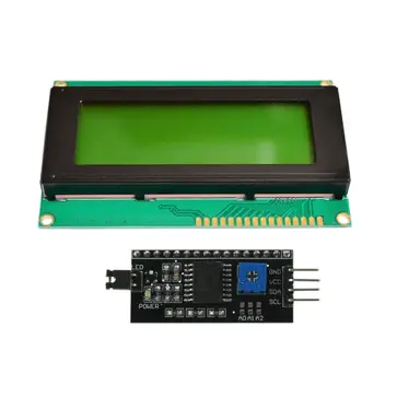
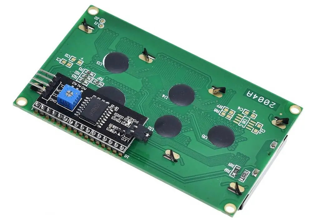
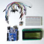
AZ-Delivery HD44780 2004 LCD Display Bundle 4×20
This beautifully packed product was supplied from Deggendorf, German. I bought it through Amazon UK which advertised, “The included E-Book provides useful information on how to begin your project, helps with a quick setup, and saves time on the configuration process.” I sent AZ an email requesting the E-Book and it arrived impressively quickly.
There was one small problem. The pdf describes how to use the bare display with its many connections but not how to use the I2C adaptor.
Luckily, I have used these before and know that you have to solder the interface board onto the display board. Normal practice is to solder it underneath with connection I2Cpins pointing out the side at the top left.
Alternatives:
- Leave it off and use the board as outlined in the AZ guide – uses too many pins!
- Solder on a row sockets; above or below the board so you can remove the backpack.
- Solder a row of sockets with long legs so that you can use the display on a breadboard or put the adapter into the sockets.
Putting the interface board on the back has the advantage of gently tilting the display forward making it easier to read while working at your bench.
You will need a small screwdriver to adjust the setting of the blue trim-pot once the display is connected and running a script.
This is another I2C device so we connect up as before. Take care as the SCL and SDA pins are in a different order from the SSD1306! The I2C address of the backpack was 0x27.
There has been a great deal of chat on the various Arduino forums over the years about these backpack boards available from many manufacturers. They come with various I2C addresses but the many libraries available, often with the same name, do not make the address configurable and will only work with a specific board.
| LCD 2004 Display | Arduino UNO |
| GND | GND |
| VCC | 5V |
| SDA | A4 |
| SCL | A5 |
Before we can run the script, we need to download a suitable library for this I2C version of the 2004 LCD. Unfortunately, AZ-Direct did not suggest a suitable site. I’ve been using the library at https://github.com/johnrickman/LiquidCrystal_I2C
and found that it works well with this interface board.
Once the library is installed, we are ready to try out the display.
Try this short script to test your connections:
/ LCD I2C 2004 Test
// Tony Goodhew 4th July 2020
// Tutorial45.com
#include <LiquidCrystal_I2C.h>
// https://github.com/johnrickman/LiquidCrystal_I2C
// Set LCD address to 0x27 with 20 chars by 4 lines display
LiquidCrystal_I2C lcd(0x27, 20, 4);  //(0x27, 16, 2) small LCD

// Character definitions - 5 cols x 7 rows
byte pi[8]  = {0,1,14,26,10,10,10};  // Compact version

byte smiley[8] = {                   // Easy but verbose version
  B00000,
  B01010,
  B00000,
  B00000,
  B10001,
  B01110,
  B00000,
};
byte sad[8] = {
  B00000,
  B01010,
  B00000,
  B00000,
  B01110,
  B10001,
  B00000,
};
void setup() {
  // Initialize the LCD
  lcd.init();
  // Create 3 new characters Max of 8 (0…7)
  lcd.createChar(0, pi);
  lcd.createChar(1, smiley);
  lcd.createChar(2, sad);

  // Set Cursor position and print text
  lcd.backlight();
  lcd.setCursor(3,0);
  lcd.print("Hello, world!");
  lcd.setCursor(3,1);
  lcd.print("Arduinos Rock");
  lcd.setCursor(0,2);
  lcd.print("Arduino LCD 2004 I2C");
  lcd.setCursor(3,3);
  lcd.print("Tutorial45.com");
  delay(2000);            //  Wait 2 seconds

  // print special characters to 4 corners of screen
  lcd.setCursor(0,3);
  lcd.write(0);
  lcd.setCursor(0,0);
  lcd.write(1);
  lcd.setCursor(19,0);
  lcd.write(2);
  lcd.setCursor(19,3);
  lcd.write(255);  // solid 5x8 block – built in
}

void loop(){}
You should be able to see clear, bright, white characters on a bright blue background. You will probably need to adjust the small blue trim-pot on the back-board to get the best contrast.
Once again, the origin is top left with the corner character at (0, 0). There are 20 characters on a line (0…19) and four rows (0…3).
We need to be very carful about running over the end of a line.
Change
lcd.print("Arduino LCD i2c 2004");
to
lcd.print("Arduino LCD i2c 2004xx*");
And change
lcd.print("Hello, world!");
to
lcd.print("Hello, world!123456");
When we run the script again, we find that line 0 overflows into line 2 and line 1 overflows onto the 3 line but the “*” gets immediately overwritten by the “T”.
This can cause some problems so take care not to overrun lines.
This script also demonstrates the definition of special characters. The user can define up to 8 characters on a 7 by 5 grid. This is easily carried out. Just look carefully at the happy and sad face definitions. The 1 bits indicate a white pixel.
byte pi[8] = {0,1,14,26,10,10,10};
| 16 | 8 | 4 | 2 | 1 | |
|---|---|---|---|---|---|
| 0 | |||||
| 1 | 1 | ||||
| 1 | 1 | 1 | 14 | ||
| 1 | 1 | 1 | 26 | ||
| 1 | 1 | 10 | |||
| 1 | 1 | 10 | |||
| 1 | 1 | 10 |
If you run the script again you will find these defined characters in the corners of the screen. The large block at the bottom right is predefined character 255. https://cdn-shop.adafruit.com/datasheets/TC2004A-01.pdf
This is a long but exciting document and shows the complete ‘built-in’ character set and how the characters you send to the screen are stored.
Here is a script to display all of the available characters.
// Display LCD 2004 character set
// Tony Goodhew 7th July 2020
// Tutorial45.com
#include <Wire.h>
#include <LiquidCrystal_I2C.h>
LiquidCrystal_I2C lcd(0x27,20,4);  // set the LCD address to 0x27 and 20x4

byte heart[8] = {0,10,31,31,14,4,0};
byte bknht[8] = {10,31,0,31,14,4,0};
byte ok[8] = {0,1,3,22,28,8,0};
byte no[8] = {0,27,14,4,14,27,0};
byte bong[8]  = {4,14,14,14,31,0,4};
byte music[8]  = {2,3,2,14,30,12,0};
byte clk[8] =  {0,14,21,29,17,14,0};
byte turn[8] = {1,1,5,9,31,8,4};

void setup(){
  lcd.init();  // initialize the lcd
  lcd.backlight();
  lcd.createChar(1, heart);
  lcd.createChar(2, bknht);
  lcd.createChar(3, ok);
  lcd.createChar(4, no);
  lcd.createChar(5, bong);
  lcd.createChar(6, music);
  lcd.createChar(7, clk);
  lcd.createChar(0, turn);
  lcd.home();

// Show the character
  int n = 0;
  while (n < 255) {
    lcd.clear();
    lcd.setCursor(0,0);
    lcd.print("ASCII Codes: ");
    lcd.setCursor(4,1);
    lcd.print("Dec: ");
    lcd.print(n);
    lcd.print("-");
    lcd.print(n+15);
    lcd.setCursor(4,2);
    lcd.print("Hex: ");
    lcd.print(n, HEX);
    lcd.print("-");
    lcd.print(n+15, HEX);
    lcd.setCursor(2, 3);
    for (int m=0; m<16; m++) {
      lcd.write(n+m);
    }
    n = n + 16;
    delay(2000);
  }
 }
void loop() {}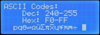
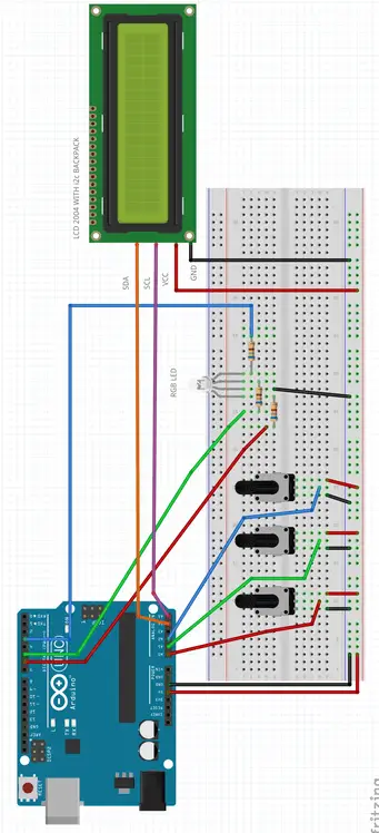
Project #3 Using Arduino with the AZ-Delivery LCD 2004 and FC-113 I2C backpack
Materials needed
- Arduino – standard or cloned UNO
- AZ-Delivery LCD 2004 and FC-113 I2C backpack Connecting wires
- 3 x 10K Ohm potentiometer
- 1 x RGB LED or single Red, green and Blue resistors
- 3 x 560 Ohm resistors – nearby value
- Breadboard or stripboard
- Connecting wire
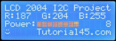
// LCD I2C 2004 Project
// Tony Goodhew 4th July 2020
// LCD i2c, Arduino, RGB LED and 3 10K Ohm potentiometers
#include <LiquidCrystal_I2C.h>
// https://github.com/johnrickman/LiquidCrystal_I2C

// Set the LCD address to 0x27 & 20 chars by 2 lines display
LiquidCrystal_I2C lcd(0x27, 20, 4);  //(0x27, 16, 2) small LCD

#define r 6  // Red LED pin
#define g 5  // Green LED pin
#define b 3  // Blue LED pin

// Character definitions - 5 cols x 7 rows
byte smiley[8] = {
  B00000,
  B01010,
  B00000,
  B00000,
  B10001,
  B01110,
  B00000,
};
byte sad[8] = {
  B00000,
  B01010,
  B00000,
  B00000,
  B01110,
  B10001,
  B00000,
};
byte block[8]  = {0,31,31,31,31,31,31};

void align(int v){                // Right align number with spaces
  if (v < 100) {lcd.print(" ");}
  if (v < 10 ) {lcd.print(" ");}
}
void setup() {
  // Initialize the LCD
  lcd.init();
  // Create  new characters - Max of 8
  lcd.createChar(0, smiley);
  lcd.createChar(1, sad);
  lcd.createChar(2, block);  // For bar graph
  lcd.backlight();

  // Set up static Text
  lcd.clear();
  lcd.setCursor(6,3);
  lcd.print("Tutorial45.com"); // Banner
  delay(1500);
  lcd.setCursor(0,0);
  lcd.print("LCD 2004 I2C Project");
  lcd.setCursor(0,1);
  lcd.print("R:     G:     B:    ");  // Headings
  lcd.setCursor(0,2);
  lcd.print("Power:            ");
}

void loop(){
  int rValue = analogRead(A0)/4;  // Get Red
  analogWrite(r, rValue);
  lcd.setCursor(2,1);
  align(rValue);
  lcd.print(rValue);
  int gValue = analogRead(A1)/4;  // Get Green
  analogWrite(g, gValue);
  lcd.setCursor(9,1);
  align(gValue);
  lcd.print(gValue);
  int bValue = analogRead(A2)/4;  // Get Blue
  analogWrite(b, bValue);
  lcd.setCursor(16,1);
  align(bValue);
  lcd.print(bValue);
  int t = (rValue + gValue + bValue) *10 / 255 / 3; // Calc Power
  lcd.setCursor(6,2);
  lcd.print("          ");  // Clear bar graph
  lcd.setCursor(17,2);      // Display power number
  align(t);
  lcd.print(t);
  lcd.setCursor(6,2);
  for (int i=0; i<t; i++) {  // Bar graph
    lcd.write(2);
  }
  lcd.setCursor(0,3); // Bottom left corner
  if (t > 5) {
    lcd.write(0);     // Happy face
  }
  else {
    lcd.write(1);     // Sad face
  }
}
Once again, we need to be careful when we overwrite. If you overwrite ‘100’ with ‘99’ you will get ‘990’. Always fill all of the character positions with new characters. It is easy to write 3 spaces, reset the cursor and write the number.
You can set the cursor to flash, but I’ve never found it useful.
After many days and e-mails back and forth with AZ-Delivery in Germany, I found that there is a separate E-book for the backpack board, called LCD16x2_FC-113.pdf – but it is only available in German.
It tells you to use the “New LiquidCrystal” library at: https://bitbucket.org/fmalpartida/new-liquidcrystal/downloads/
and provides this minimal script (adapted for 20 characters and 4 lines) to get you started:
// Uses the new-liquidcrystal_i2c library
// https://bitbucket.org/fmalpartida/new-liquidcrystal/downloads/
// This is the Test Script from AZ-Delivery matched with the
// FC-113 Serial LCD Adapter Board Module I2C Interface
#include <Wire.h>
#include <LCD.h>
#include <LiquidCrystal_I2C.h>
LiquidCrystal_I2C lcd(0x27,2,1,0,4,5,6,7,3,POSITIVE); // Set the LCD I2C address
void setup()
{
lcd.begin(20,4);
lcd.clear();
lcd.setCursor(0,0);
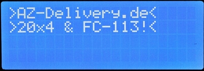
lcd.print(">AZ-Delivery.de<");
lcd.setCursor(0,1);
lcd.print(">20x4 & FC-113!<");
}
void loop()
{
lcd.setBacklight(HIGH); // blink the backlight
delay(1000);
lcd.setBacklight(LOW);
delay(1000);
}
Conclusion
This screen is large and much easier to read. Its update rate is quite slow. If you re-write the whole screen in one go, you can see a ripple across the display. The main drawback is that it cannot display graphical objects.
There is a slight problem with the documentation supplied to English-speaking customers by AZ-Delivery. However, the suppliers of the SSD1306 boards provided no help or documentation. Finding a suitable Arduino library that works properly could be a problem. The SSD1602 and 2004 LCDs are very popular with Arduino users and the I2C backpack does leave more pins free for your projects.
Project suggestions
- Define some more characters.
- Connect up some sensors and display the values received on the screen. You could use temperature, humidity, air pressure, distance, tilt, or accelerometer sensors.
Comparing the boards
| SSD1306 128×64 | SSD1306 128×32 | LCD 2004 | |
| Advantages | Excellent graphics3 sizes of charactersExcellent support libraryVery clear – high contrastOnly needs 2 pinsInexpensiveFree cables | Excellent graphics3 sizes of charactersExcellent support libraryVery clear – high contrastOnly needs 2 pins(2 in the packet)Cheap | Very easy to readLarge charactersEasy to see from a distanceOnly needs 2 pins with backpack |
| Disadvantages | A bit small | Probably too small | Cannot display graphicsFinding a suitable library |
Overview
I’ve had the LCD 1602 and LCD2004 boards in my possession for quite a while now, acquiring them shortly after my initial Arduino purchase. Their utility has been significantly increased by the backpack. The larger SSD1306 board has been in use by me for approximately 18 months and I have found it to be exceedingly beneficial. The scope of what one can do with this small display is expansive. Which board to choose essentially comes down to ‘horses for courses’; it depends on the specifics of your project and the viewing distance required.
Related posts:
 Arduino Projects: Building an Arduino Countdown Timer
 Arduino Projects: LED – 4X4X4 LED Cube
 Arduino Projects: PIR Motion Sensor
 The Best Arduino Starter Kits
 Arduino Relay Project
 Arduino Projects: Building a Mini Arduino Shield With KiCAD – Part 1
 Arduino MOSFET Project
 6 Reasons to Build Your Next Arduino Project With XOD