Adding LEDs to a project soon uses up valuable pins. What if you could control a row of 12 LEDs to show changing values with only 4 digital pins? There is a way and it is called Charlieplexing. It was first proposed in 1995 by Charlie Allen.
It relies on two properties that you may not have previously considered useful.
LEDs are Light Emitting Diodes and only pass electrical current in one direction. If you connect two of them together, in parallel but facing in opposite directions, you can use just 2 wires to control them.
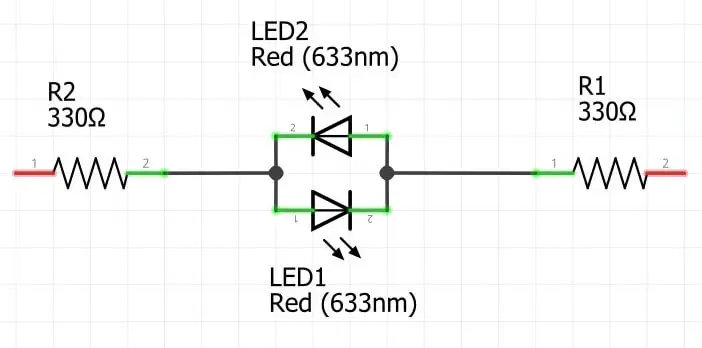
If we connect the right-hand end of the circuit to 5V and the left-hand end to GND current will flow from right to left and the upper LED, #2, to light up and the lower LED will stay dark. If we reverse the connections, current will flow in the opposite direction and only the lower LED, #1, will be lit.
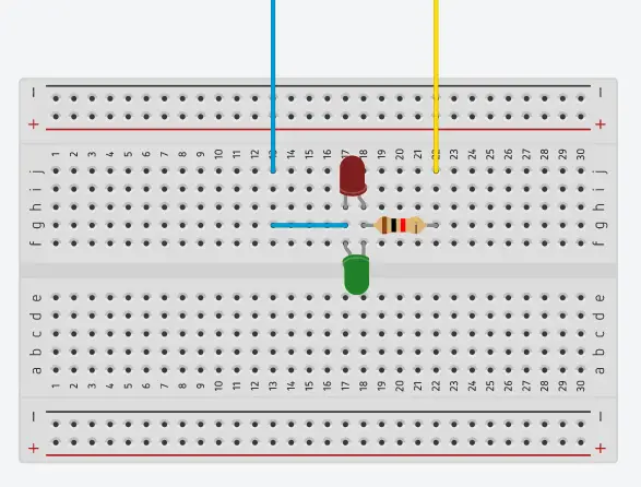
Here is the same setup on a breadboard. I’ve only used one resistor here, 660 Ohms, but it protects both LEDs. Notice that the long legs of the LEDs, the anodes, which are connected to the higher voltage, face in opposite directions.
Project #1 – 6 LEDs on 3 wires
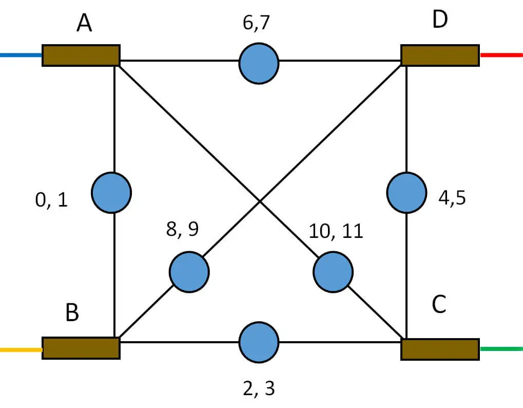
If we want more than two LEDs we can add additional pairs of parallel, opposite facing LEDs in different arrangements. Let’s try 6 LEDs in three pairs in the form of a triangle. The blue circle represents a pair of opposed parallel LEDs.
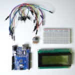
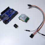
Required materials
- Arduino – an UNO works perfectly
- LEDs – space constraints in project #2 make 3mm LEDs a better proposition
- 330 Ohm resistors
- Breadboard or stripboard
- Connecting wire
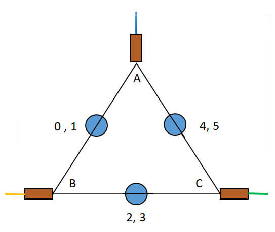
We can add the 330 Ohm resistors, the brown rectangles, to each of the corners, to limit the current, protect the LEDs and the Arduino pins. I’ve shown blue, yellow and green wires connected to the resistors.
| BLUE | YELLOW | GREEN | LED ON |
| HIGH | LOW | ? | 0 |
| LOW | HIGH | ? | 1 |
| ? | HIGH | LOW | 2 |
| ? | LOW | HIGH | 3 |
| LOW | ? | HIGH | 4 |
| HIGH | ? | LOW | 5 |
The question marks indicate that the wire is not connected. How can we effectively disconnect a wire while it is physically attached to an Arduino pin?
The second property that we seldom think about is that the digital microcontroller pins are tri-state. They can be set HIGH, LOW or used for INPUT. When a pin is set to INPUT MODE it is high impedance. So high that almost no current can flow so it is effectively disconnected.
This means we can control the 6 LEDs with three pins connected to the blue, yellow and green wires and replace the ‘?’ with INPUT mode rather than the OUTPUT mode used for HIGH and LOW.
Normally we just set a pin’s mode at the start of the script and leave it alone for the rest of the program. Here we need to keep switching modes and values.
Here is one way of coding the previous table:
// LED numbers    0,1,2,3,4,5
byte anodes[]  = {b,y,y,g,g,b};  // HIGH
byte caths[]   = {y,b,g,y,b,g};  // LOW
byte inputs[]  = {g,g,b,b,y,y};  // INPUT
b, y, and g are the wire colors, which have been allocated digital pin numbers. Reading vertically, for LED#0 to be switched ON – BLUE is set to HIGH (anode), YELLOW is set to LOW (cathode), and GREEN is set as an INPUT (disconnected).
The arrangement of LEDs in the previous diagram is logical but not very useful. It would be much more helpful if the LEDs were in a straight line. This is quite a tricky topological transformation to keep all the connections correct. What you gain is free pins involve more complicated wiring.
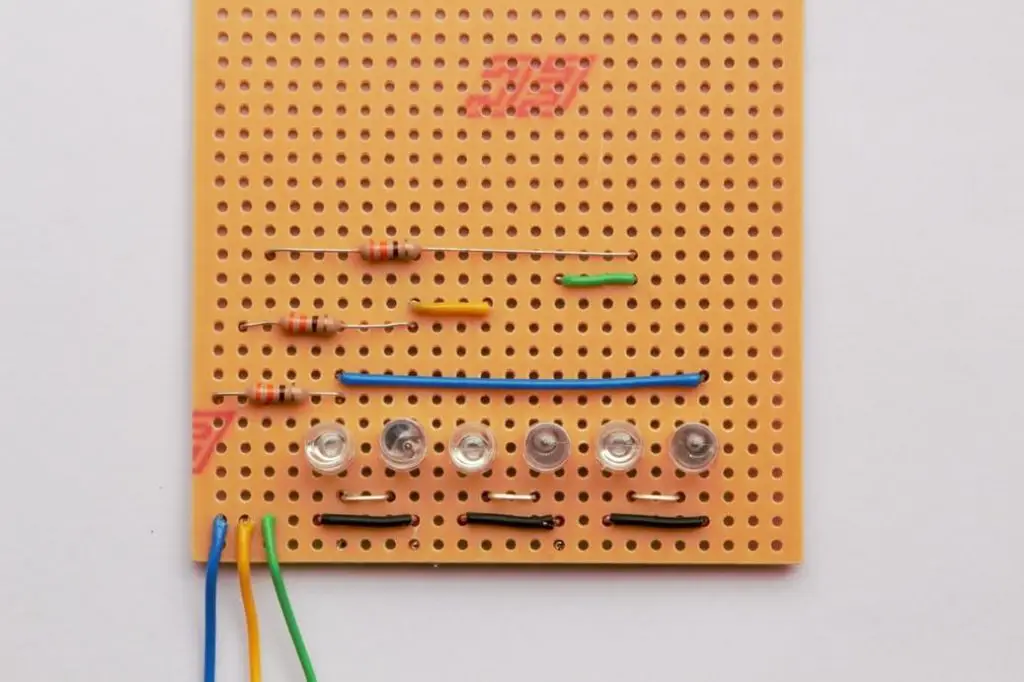
Here is the breadboard version:
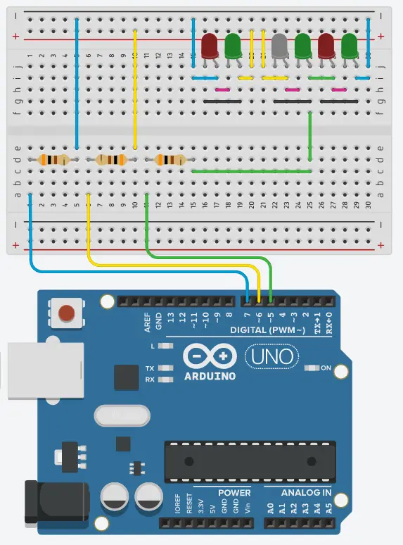
Notice that all the LEDs face the same way with their anode, the longer leg, to the right. Each pair is cross-connected, anode to cathode, with the pink and black links. The blue and yellow wires drive the first pair, the second pair by the yellow and green wires, and the last pair by the green and blue wires. The colored wire is connected directly to the anode of the LED, and it needs to turn ON.
Above each LED is its number (0…5) and the wire colors, anode – cathode. This is quite an effort to link up, and the DuPont wires would probably get in the way when observing the flashing LEDs. Below is a photograph of a stripboard version, which, once soldered up, could easily be used in multiple projects. (There are no underside cuts of the copper strip on this board)
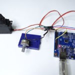
I connected the board to an Arduino UNO with the blue wire on pin 7, the yellow on pin 6, and the green on pin 5. I also added a 10 K Ohm potentiometer with the wiper on A0 and the outside connections to 5V and GND to give physical input to the program. You need to twist the pot knob once the LEDs stop flashing left to right.
// CharliePlexing 6 LEDs with multiplexed bar graph
// Tony Goodhew 27 June 2020

#define b 7   // Blue wire
#define y 6   // Yellow wire
#define g 5   // Green wire

#define potPin A0  // 10 K Ohm potentiometer on A0, 5V and GND
int done = false;
int wait = 190;
unsigned long startTime;

// LED numbers    0,1,2,3,4,5
byte anodes[]  = {b,y,y,g,g,b};  // HIGH
byte caths[]   = {y,b,g,y,b,g};  // LOW
byte inputs[]  = {g,g,b,b,y,y};  // INPUT

void show(int p){  // Turn on a single LED ( p = 0...5)
  pinMode(inputs[p], INPUT);   // Disconnect
  pinMode(caths[p], OUTPUT);
  digitalWrite(caths[p], 0);   // GND
  pinMode(anodes[p], OUTPUT);
  digitalWrite(anodes[p], 1);  // 5V
}

void show2(int q) {  // Multiple LEDs from left
  for (int m = 0; m < q; m++)  {
    show(m);
    delay(3);
  }
}

void setup() {
  Serial.begin(115200);  // Ready for de-bugging
  startTime = millis();
}

void loop() {
  if (!done) {  // Basic left to right movement
    for (int m = 0; m < 10; m++){  // Cycles
      for (int i = 0; i <6; i++){  // LEDs
        show(i);
        delay(wait);
        wait = wait - 3;           // Speed things up
      }
    }
  }
  done = true;  // Finished with counted display

  // Twist the pot to change the LED lit up
  int potValue = analogRead(potPin); // Read potentiometer
  int pointer = potValue / 160; // values 0...6
  if (pointer == 0 ) {  // Turn off all LEDs
    pinMode(b, INPUT);  // Disconnect all wires
    pinMode(y, INPUT);
    pinMode(g, INPUT);
  }
  else{
    if (millis() - startTime < 17000) { // 17 seconds
      show(pointer - 1); // Single LED
    }
    else {
      show2(pointer);    // Bar graph
    }
  }
}
The function show() does most of the work. It resets pin modes and values to switch on a single LED. It is called multiple times by the function show2(), which turns a row of LEDs ON/OFF so quickly that persistence of vision does not allow our eyes to notice the flashing and produces the appearance of a steady a bar graph, if slightly dimmed.
In the main loop there are three stages of display:
- A single lit LED appears to move from left to right at faster and faster speeds.
- A single LED is lit and its position in the row is controlled by the potentiometer.
- A bar graph of lit LEDs is controlled by the potentiometer – 17 sec into the main loop.
Here is a second script that demonstrates generating patterns with this limited number of LEDs.
// CharliePlexing 6 LEDs Patterns
// Tony Goodhew 28 June 2020

#define b 7   // Blue wire
#define y 6   // Yellow wire
#define g 5   // Green wire

// LED numbers    0,1,2,3,4,5
byte anodes[]  = {b,y,y,g,g,b};
byte caths[]   = {y,b,g,y,b,g};
byte inputs[]  = {g,g,b,b,y,y};

void show(int p){  // Turn on a single LED ( p = 0...5)
  pinMode(inputs[p], INPUT);   // Disconnect
  pinMode(caths[p], OUTPUT);
  digitalWrite(caths[p], 0);   // GND
  pinMode(anodes[p], OUTPUT);
  digitalWrite(anodes[p], 1);  // 5V
}

void show2(int q) {  // Mulitple LEDs from left
  for (int m = 0; m < q; m++)  {
    show(m);
    delay(3);
  }
}

void setup() {
  Serial.begin(115200);  // Ready for de-bugging
}

void loop() {
  // Opposites
  for (int m = 0; m < 7; m++){        // Cycles
    for (int i = 0; i <6; i++){       // Move up
      for (int t = 0; t <50; t++)  {  // Flashes 50 times
        show(i);                      // Left LED
        delay(3);                     // 3 millisecond flash
        show(5-i);                    // Right LED
        delay(3);
      }
    }
  }

  // Pair
  for (int m = 0; m < 7; m++){         // Cycles
    for (int i = 0; i < 4; i++){       // Move up
      for (int t = 0; t <100; t++)  {  // Flashes
        show(i);                       // Left LED
        delay(3);
        show(i + 1);                   // Right LED
        delay(3);
      }
    }
    for (int i = 0; i < 4; i++){      // Move down
     int ii = 4 - i;
     for (int t = 0; t <100; t++)  {  // Flashes 50 times
        show(ii);                     // Left LED
        delay(3);
        show(ii + 1);                 // Right LED
        delay(3);
      }
    }
  }
}
Project #2 – 12 LEDs with 4 wires
We can arrange the 6 pairs of LEDs in a square with a resistor at each corner.
image
We can code this in a similar way to the previous script but we will need to set two lines as inputs.
// LED numbers 0,1,2,3,4,5,6,7,8,9,10,11
byte anodes[] = {b,y,y,g,g,r,r,b,y,r, b, g};
byte caths[] = {y,b,g,y,r,g,b,r,r,y, g, b};
byte input1[] = {g,g,b,b,b,b,y,y,b,b, r ,r};
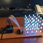
byte input2[] = {r,r,r,r,y,y,g,g,g,g, y, y};Here is a photograph of the stripboard version. The boards were 24 holes wide so there was just enough room to place twelve 3mm LEDs across the width of the board. (5mm LEDs are too wide, unfortunately, and need a single hole space between them).
Once again all the LEDs are facing the same way with the longer leg, anode, to the right. The copper strips on the underside of the board, underneath the resistors, are cut.
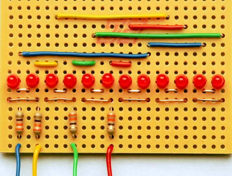
The board is well worth soldering up and keeping for use in other projects.
// CharliePlexing 12 LEDs
// Tony Goodhew 27 June 2020

#define b 7   // Blue wire
#define y 6   // Yellow wire
#define g 5   // Green wire
#define r 4   // red wire
#define potPin A0  // 10 K Ohm potentiometer on A0

// pin numbers    0,1,2,3,4,5,6,7,8,9,10,11
byte anodes[]  = {b,y,y,g,g,r,r,b,y,r, b, g};
byte caths[]   = {y,b,g,y,r,g,b,r,r,y, g, b};
byte input1[]  = {g,g,b,b,b,b,y,y,b,b, r, r};
byte input2[]  = {r,r,r,r,y,y,g,g,g,g, y, y};

void show(int p) {  // Turn on a single LED ( p = 0...5)
  pinMode(input1[p], INPUT);     // Disconnect
  pinMode(input2[p], INPUT);
  pinMode(caths[p], OUTPUT);
  digitalWrite(caths[p], 0);   // GND
  pinMode(anodes[p], OUTPUT);
  digitalWrite(anodes[p], 1);  // 5V
}

void show2(int p) {
  for (int m = 0; m < p; m++)  {
    show(m);
    delay(2);  // Reduced wait time to remove flicker
  }
}

void setup() {
  Serial.begin(115200);  // Ready for de-bugging
}

void loop() {
  int potValue = analogRead(potPin); // Read potentiometer
  int pointer = potValue / 80; // values 0...12
  if (pointer == 0) {
    pinMode(b, INPUT);  // Turn off all LEDs
    pinMode(y, INPUT);  // Disconnect all wires

    pinMode(g, INPUT);
    pinMode(r, INPUT);
  }
  else{
    show2(pointer);     // Bar graph display
  }
}
This is just an update of the previous code to allow for the extra LEDs and save you typing. This is just the minimum to check wiring. Note that the time delay in the show2() loop has been reduced to remove flicker. Try 3 or 4 milliseconds to see the difference.
Things to try
Modify the code to extend the patterns supplied for the 6 LED board:
- One LED moving left and right at speeds controlled by the potentiometer
- 2 or 3 LEDs moving together left and right or mirroring
- Bar graph with input from a different sensor such as an ultrasonic distance sensor (SR04) or temperature sensor (TMP36 or DS18B20).
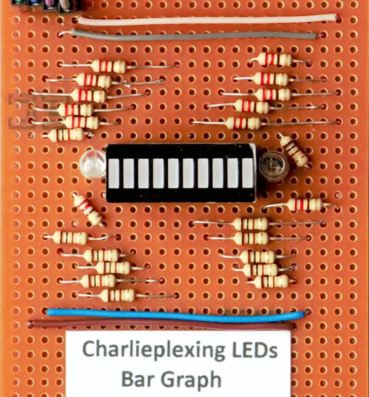
- Wire up a compact 10 segment bar graph display and control it with 4 pins. I put an additional normal red LED at one end and a green LED at the other. If you try this remember to cut the tracks under the bar graph display. The display has cathodes on one side and anodes on the other with the LED between them. Using the resistors to make the connections is much quicker than stripping the insulation from wires. I suggest you test each LED as you build these boards, this is much easier than fault finding at the end.
Conclusion
I trust you enjoyed the topic and consider constructing one of the boards yourself. While we may save on the number of pins used to operate these boards, the complex nature of the wiring and code compensates for this. Our exploration does not have to conclude with 12 LEDs. The control capacity for the number of LEDs increases with every additional wire introduced, as per the formula
L = n(n-1)
where L is the maximum number of LEDs controlled and n the number of pins used.
| Pins | 2 | 3 | 4 | 5 | 6 | 7 | 8 |
| LEDs | 2 | 6 | 12 | 20 | 30 | 42 | 56 |
Another useful application would be on an interactive map or school project display with individual button switches on a menu lighting LEDs at different positions on the display. Examples include naming the features of an ancient castle or tourist attractions on a map of the local area.
Related posts:
 Arduino Projects: Building an Arduino Countdown Timer
 Arduino Projects: LED – 4X4X4 LED Cube
 Arduino Projects: PIR Motion Sensor
 The Best Arduino Starter Kits
 Arduino Relay Project
 Arduino Projects: Building a Mini Arduino Shield With KiCAD – Part 1
 Arduino MOSFET Project
 6 Reasons to Build Your Next Arduino Project With XOD