This guide presumes that the user is adept in integrating LEDs, potentiometers, and sensors into the Arduino platform, has worked with SPI and I2C devices, and is prepared to level up and initiate data exchange between Arduinos. Employing this network is more straightforward and more comprehensible than radio communication; however, it necessitates wiring between the Arduinos.
CAN, a robust vehicle data bus standard, facilitates communication and data sharing among microcontrollers without needing a host computer. This message-based protocol was initially created to conserve copper in automotive wiring systems.
Bosch, the German company, came up with CAN in 1983, which was first applied in the Mercedes-Benz W140 in 1991. Modern vehicles may incorporate approximately seventy electronic devices such as sensors, actuators, a unit for managing the engine, and an automatic engine start/stop system.
These rely on getting readings from accelerometers, thermometers, and gas sensors and sending commands to actuators. Great accuracy is required, and the CAN bus has a great deal of cyclic redundancy checking (CRC) built in to ensure safety.
Small data frames are used with a maximum of 8 data bytes in each packet. Each node has an ID number, and transmission clashes on the network are dealt with by the lower-priority frame backing off. Priority depends on the allocated ID given to the device. Lower ID numbers have higher priority.
All devices, including the transmitting device, receive data packets sent on the network. The system allows one device to request data from another via a Remote Transmission Request (RTR) frame, but some authorities recommend not using this facility.
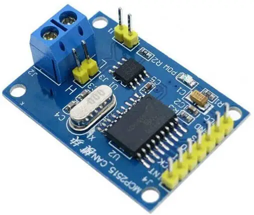
Although initially designed for automotive situations, this bus offers a simple and inexpensive system for hobby electronics projects. The node modules are available from a wide range of sources. Many use an MCP2515 CAN Bus controller with an SPI interface and an MCP2551 CAN transceiver.
The fields of a standard CAN frame
| Field | Bits |
| Start of Frame SOF | 1 |
| Standard Identifier ID | 11 |
| Control | 6 |
| Data | 64 – 8 bytes |
| Cyclic Redundancy Check – CRC | 16 |
| Acknowledgement – ACK | 2 |
| End of Frame – EOF | 7 |
A minimum of two nodes is connected with a twisted pair of wires with a nominal impedance of 120 Ohms. The CAN high (CANH) and CAN low (CANL) pins are provided on the modules. CANH is connected, and CANL is connected with 120 Ohm resistors included at the end nodes of the bus.
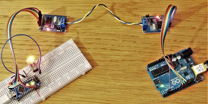
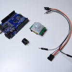
Breakout board node modules are readily available, and I used some supplied by AZ-Delivery. (A 3-pack costs less than two singles!) SPI signals drive the modules and are very easy to connect to Arduino boards. I used a Nano at one end and a UNO at the other end of the network. Jumpers were used to short the J1 pins to include the built-in 120 Ohm termination resistors.
The pins on J4 were connected to the Arduinos using pins 10 to 13. The large blue screw terminals labeled H and L were used to link the modules together with the network-twisted pair of wires. I added an LED with a protective current limiting resistor to pin D5 on the Nano.
System Test
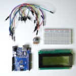
We will need:
- 2 CAN modules
- Arduino UNO
- Arduino Nano – They need different COM values
- Suitable USB cables
- Connection wire
- LED
- 560 Ohm resistor
Connections
| CAN Module | Arduino UNO and Nano |
| INT | D6 (Not needed for these examples) |
| SCK | D13 |
| SI | D11 |
| SO | D12 |
| CS | D10 |
| GND | GND |
| VCC | 5 volts |
| H | H on the other module |
| L | L on the other module |
| J1 pins shorted together (to provide 120 Ohm network termination.) |
Library
You need an Arduino library to drive these boards. There are several to choose from, but I picked mcp_can, which can be found here: https://github.com/Seeed-Studio/CAN_BUS_Shield
because it had several example sketches. This is supplied as a .zip file and is easy to install.
At this point, you need a bit of care and organization. If using Windows, you will need two separate instances of the Arduino IDE running on your computer with different ports / COM numbers. You need to start each of them from the Start button. (Do not try to get the second one by clicking NEW on the first IDE window.)
Keep the sending setup on the right. (UNO right side of the bench, USB cable in the right USB socket, IDE and Serial Monitor windows on the right side of the screen – COM27.)
Keep the receiving setup on the left. (Nano, with optional LED on pin D5, USB socket, IDE, and Serial Monitor on the left – COM11.)
Check the port numbers at the bottom right corner of each IDE window. They must be different.
Copy the SEND sketch into the right IDE and compile/load it. Then copy the RECEIVE sketch into the left IDE and compile/load it.
Turn on the Serial monitors (115200 baud) and press the reset button on the right, sending Arduino UNO to start sending data again.
Both monitor windows should fill up so that you can see data flowing via the network from one to the other.
Basic SEND sketch
// Demonstration SEND with CAN-BUS Module - UNO
// Tony Goodhew 18th Nov 2020
// Tutorial45.com
#include <mcp_can.h>
#include <SPI.h>

const int SPI_CS_PIN = 10;

MCP_CAN CAN(SPI_CS_PIN); // Chip select

void setup() {
    Serial.begin(115200);

    while (CAN_OK != CAN.begin(CAN_500KBPS)) {
        Serial.println("CAN BUS Module failed to start");
        Serial.println(" Try again");
        delay(100);
    }
    Serial.println("CAN BUS Module started.");

    for (int i=0; i <256; i++){
      Serial.println("-----------------------------");
      int q = random(0,100);
      int ledState = 1;
      if (q < 40){ledState = 0;}
      // Place data to be sent in output buffer
      byte bufout[8] = {ledState, i, i+1, 255, 100, 200, random(0,255), 255-i};

      // Sending:  ID = 0x05, standard frame, data len = 8, data in bufout
      CAN.sendMsgBuf(0x05, 0, 8, bufout);
      Serial.print("Packet sequence # ");
      Serial.println(i);
      for(int i = 0; i<8; i++){
          Serial.print(bufout[i]);
          Serial.print("\t");
      }
      Serial.println();
      delay(100);       // slow things down
    }
}
void loop(){}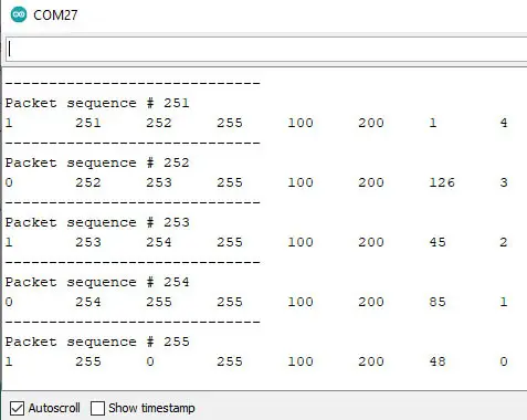
This sketch sends 256 packets of data across the network. Each packet is made up from the ID of the sending node, “05” hex, and 8 bytes:
- randomly generated 0 or 1, to turn the LED ON/OFF,
- sequence value 0 to 255
- sequence value + 1 – note it overflows on last frame (“0” not “256”)
- constant 255
- constant 100
- constant 200
- random numbers 0 to 255
- sequence counting down from 255 to 0
Basic RECEIVE sketch
// Demonstration RECEIVE with CAN-BUS Module - Nano
// LED on pin 5
// Tony Goodhew 18th Nov 2020
// Tutorial45.com
#include <SPI.h>
#include <mcp_can.h>

const int spiCSPin = 10;
const int ledPin = 5; // With protection resistor

MCP_CAN CAN(spiCSPin);

void setup(){
    Serial.begin(115200);
    pinMode(ledPin,OUTPUT);

    while (CAN_OK != CAN.begin(CAN_500KBPS)) {
        Serial.println("CAN BUS Module failed to start");
        Serial.println(" Try again");
        delay(100);
    }
    Serial.println("CAN BUS Module started.");
}

void loop(){
    byte len = 0;
    byte bufin[8];

    if(CAN_MSGAVAIL == CAN.checkReceive()){
        CAN.readMsgBuf(&len, bufin);
        unsigned long canId = CAN.getCanId();
        Serial.println("-----------------------------");
        Serial.print("Data from ID: 0x");
        Serial.println(canId, HEX);

        for(int i = 0; i<len; i++){
            Serial.print(bufin[i]);
            Serial.print("\t");
            // Update LED state from 1st data item
            if(i==0)
              {digitalWrite(ledPin, bufin[0]);}
        }
        Serial.println();
    }
}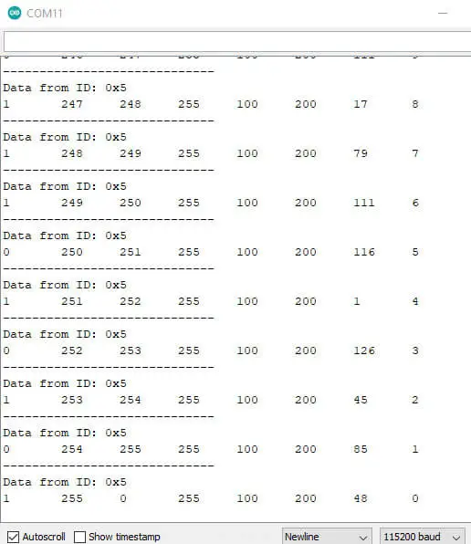
All data arrived safely with the LED flashing as required.
Project: Sending data both ways
The project reuses the circuit from the prior example to exhibit bi-directional data transmission. In this case, the Nano transmits readings of temperature and humidity collected from a simulated sensor to the UNO. Simultaneously, the UNO forwards a sequence number and multiple pre-recorded brightness values to the Nano. This data prompts the Nano to adjust the luminosity of the D5-pin LED. The activity is recorded at both ends to observe the ongoing operation.
I have simulated the sensor to have a temperature range from -40 to 100 and use brightness values between 0 and 119. Simulation allows us to concentrate on the CAN bus rather than the sensors, which you may not have handy.
The CAN bus has built-in collision avoidance arbitration. If two nodes try to send data packets simultaneously, the one with the higher priority gets precedence, and the lower priority node tries again after a short delay when the bus is clear.
We can use delay(XX); on the Arduino end because it sends more data and only processes received data every 0.5 seconds. The Nano needs non-blocking timing because it needs to keep processing incoming data while occasionally sending out data.
Sometimes, we need to ‘code’ a data item so that it can be transmitted with bite-sized pieces. A byte can contain values from zero to 255. If we need to send integer temperatures ranging from -40 to 100 a simple trick is to add 40 before you send it, and take 40 off again once it has arrived.
If you want to send floating point temperatures, you could split the temperature into whole numbers and fractional parts. Send the whole number part in the same manner in one byte and the decimal part multiplied by 100 in a second byte. At the receiving end, divide the ‘decimal byte’ by 100 and recombine by addition to get the original temperature.
Nano Code
// Demonstration RECEIVE and SEND with CAN-BUS Module - NANO
// LED on pin 5 with 560 Ohm - PWM available
// Tony Goodhew 24th Nov 2020
// Tutorial45.com
#include <SPI.h>
#include <mcp_can.h>
const int spiCSPin = 10;
const int ledPin = 5; // With protection resistor- PWM pin
// Simulated temperature and humidity values
const int temps[] ={-40,-34,-27,-15,0,5,11,15,17,24,34}; // 11 items
const int hums[] = {20,30,40,50,60,75,80,95,72,56,48,35}; // 12 items
int tp = 0; // temperature data pointer
int hp = 0; // humidity data pointer
unsigned long nextTime; // For non-blocking delays
MCP_CAN CAN(spiCSPin);
void setup(){
Serial.begin(115200);
pinMode(ledPin,OUTPUT);
nextTime = 500 + millis(); // 0.5 seconds in the future
while (CAN_OK != CAN.begin(CAN_500KBPS)) {
Serial.println("CAN BUS Module failed to start");
Serial.println(" Try again");
delay(100);
}
Serial.println("CAN BUS Module started.");
}
void loop(){
byte len = 0;
byte bufin[8];
if(CAN_MSGAVAIL == CAN.checkReceive()){ // Data packet available?
CAN.readMsgBuf(&len, bufin); // Read data packet
unsigned long canId = CAN.getCanId(); // Get the ID of sender
Serial.print("Data from ID: 0x");
Serial.print(canId, HEX);
Serial.print("\t");
if (canId == 0x05){ // Is it from UNO?
for(int i = 0; i<len; i++){ // Print the contents of packet received
Serial.print(bufin[i]);
Serial.print("\t");
}
Serial.println();
// Update LED brightness from second data item
analogWrite(ledPin, bufin[1]);
}
}
// Every 0.5 seconds
if (millis() > nextTime){ // Has 0.5 seconds passed since last send?
nextTime = nextTime + 500; // Update next time to send
// Simulate sensors
int temperature = temps[tp]; // Fetch simulated temperature
tp = tp + 1;
if (tp > 11){tp = 0;}
int humidity = hums[hp]; // Fetch simulated humidity
hp = hp + 1;
if (hp > 12){hp = 0;}
byte temp = byte(temperature + 40); // code so never negative
byte hum = byte(humidity);
byte bufout[] = {temp, hum}; // Put send data into buffer
CAN.sendMsgBuf(0x20, 0, 2, bufout); // Id = 0x20 // Send the packet
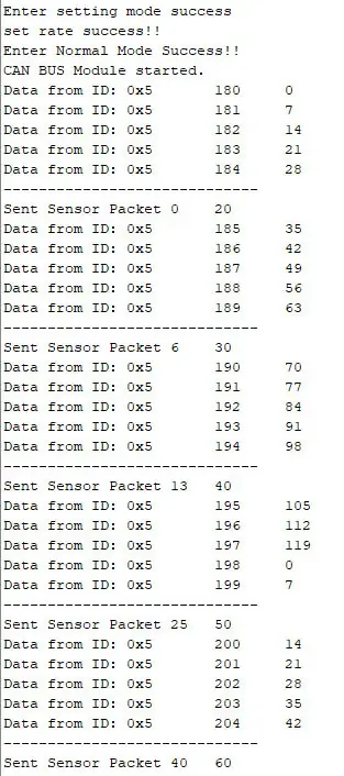
Serial.println("-----------------------------"); // Log packet sent to Serial Monitor
Serial.print("Sent Sensor Packet ");
for(int i = 0; i<2; i++){
Serial.print(bufout[i]);
Serial.print("\t");
}
Serial.println();
}
}
Uno Code
// UNO - SEND & RECEIVE with CAN-BUS Module
// Tony Goodhew 24th Nov 2020
// Tutorial45.com
#include <mcp_can.h>
#include <SPI.h>
const int SPI_CS_PIN = 10;
byte len = 0;
byte bufin[8];
MCP_CAN CAN(SPI_CS_PIN); // Chip select
byte brightness = 0;
byte sequence = 0;
void setup() {
Serial.begin(115200);
while (CAN_OK != CAN.begin(CAN_500KBPS)) {
Serial.println("CAN BUS Module failed to start");
Serial.println(" Try again");
delay(100);
}
Serial.println("CAN BUS Module started.");
}
void loop(){
if(CAN_MSGAVAIL == CAN.checkReceive()){ // Data packet available?
CAN.readMsgBuf(&len, bufin); // Read data packet
unsigned long canId = CAN.getCanId(); // Get the ID of sender
if (canId != 0x05){ // Is it from another node?
Serial.println("-----------------------------");
Serial.print("Data from ID: 0x");
Serial.print(canId, HEX);
Serial.print("\t");
for(int i = 0; i<len; i++){
Serial.print(bufin[i]);
Serial.print("\t");
}
Serial.println();
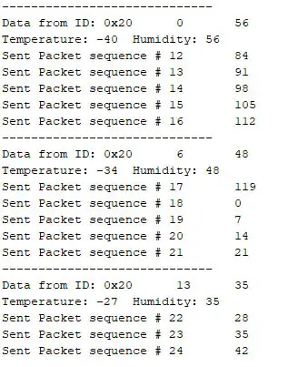
int temperature = bufin[0] - 40; // decode temperature
int humidity = bufin[1]; // get humidity
Serial.print("Temperature: "); // Log to Serial monitor
Serial.print(temperature);
Serial.print(" Humidity: ");
Serial.println(humidity);
}
}
// Sending: ID = 0x05, standard frame, data len = 8, data in bufout
brightness = brightness + 7; // Simulate turning potentiometer up
if (brightness > 120) {brightness = 0;}
sequence = sequence + 1; // Increment sequence counter
if (sequence > 255) {sequence = 0;}
byte bufout[] = {sequence, brightness}; // Put values in output buffer
CAN.sendMsgBuf(0x05, 0, 2, bufout); // Send the data packet
Serial.print("Sent Packet sequence # "); // Log action
for(int i = 0; i<2; i++){
Serial.print(bufout[i]);
Serial.print("\t");
}
Serial.println();
delay(10 0); // slow things down
}
Things to try
- Try adjusting the delays in the sketches and see what happens in the logs.
- Modify the code to send floating point temperature and humidity values.
- Add a real potentiometer to the UNO and use it to control the brightness of the LED on the Nano in real time.
- Connect a button switch and an LED to each Arduino and try controlling the LEDs across the network.
- Add an RGB LED to the Nano and control the color with three potentiometers on the UNO.
- Add a display such as an SSD1306 to the Arduino to display the temperature and humidity values received.
- Add a DHT22 sensor to the Nano and send real data rather than simulated.
- Add additional nodes with more sensors. (If connected to the middle of the data bus they will not need jumpers on J1.)
I was very pleased to find how easy it was to get Arduinos ‘talking’ to each other with these inexpensive little boards, and I hope you will try them.
Related posts:
 Arduino Projects: Building an Arduino Countdown Timer
 Arduino Projects: LED – 4X4X4 LED Cube
 Arduino Projects: PIR Motion Sensor
 Arduino Relay Project
 Arduino Projects: Building a Mini Arduino Shield With KiCAD – Part 1
 Arduino MOSFET Project
 6 Reasons to Build Your Next Arduino Project With XOD
 Learn How to Use a Multimeter Like A Pro