Today, we will build a line follower robot. This project is a little bit similar to the Arduino robot we made here some time ago. But there are some differences between them. The biggest one is the price, today’s project is probably the most affordable way to start with robotics.
This robot is also different than the one that uses the Arduino because there is no microcontroller in this project. This type of robot is called BEAM. According to Wikipedia:
BEAM robotics (Biology, Electronics, Aesthetics, and Mechanics) is a style of robotics that primarily uses simple analog circuits, such as comparators, instead of a microprocessor in order to produce an unusually simple design. While not as flexible as microprocessor-based robotics, BEAM robotics can be robust and efficient in performing the task for which it was designed.
In our case, the biggest advantage is simplicity. That’s a really simple circuit so you can easily learn how it works from the schematic that can be found in the instruction manual. You will also learn how to solder electronic components which are very important if you are interested in electronics.
Let’s start by taking a look at what we can find in the box.
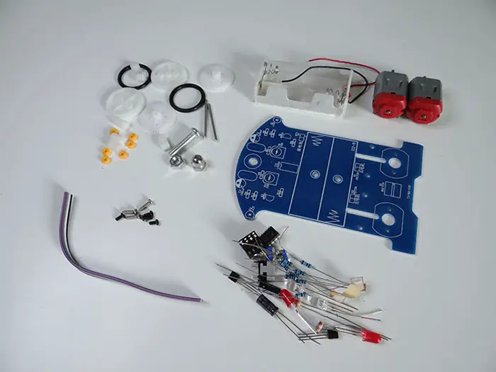
As you can see, there are not only electronic components but also mechanical components.
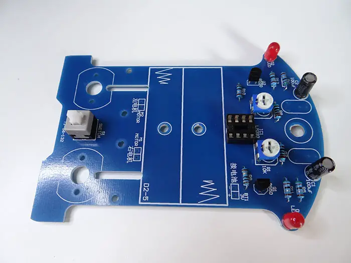
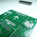
We will mount everything to the PCB first before handling the other parts.
As always we will start with the smallest components because it is much easier to solder everything that way.
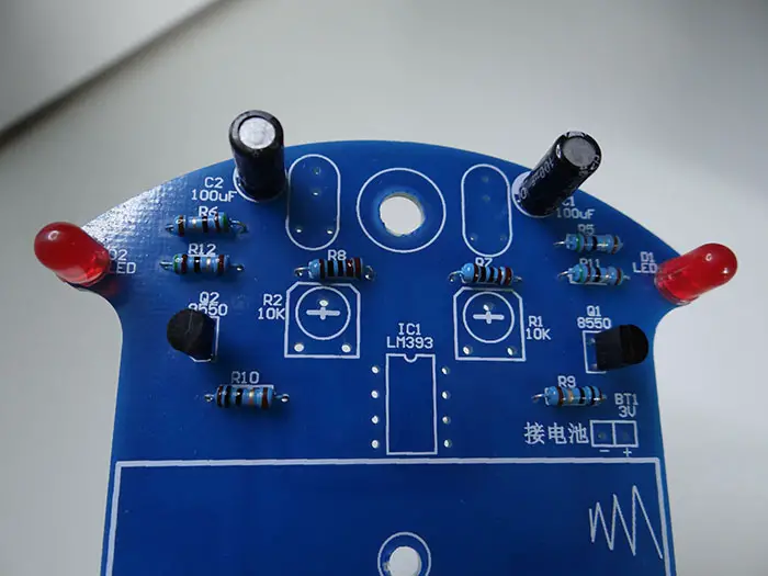
There are 3 values of resistors, to make sure you are using the right one at the right place, use a multimeter to check the values of the resistors.
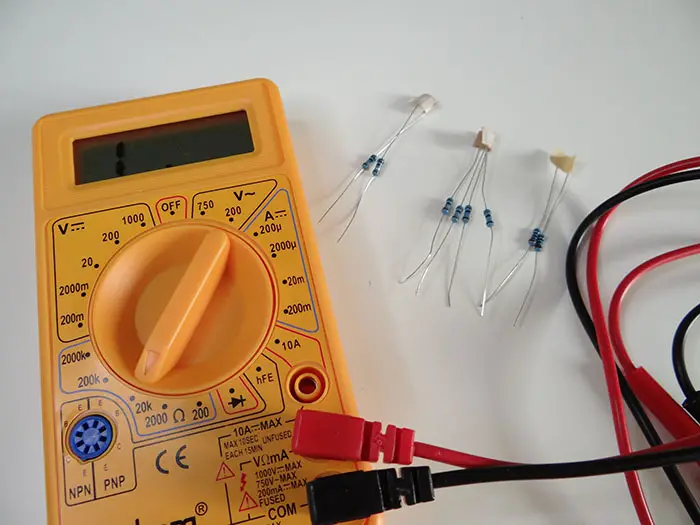
If you don’t have a multimeter, just use the image below to know where to put the different resistors.
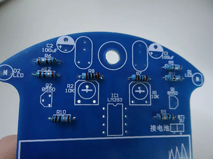
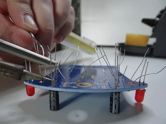
To make the resistors stuck in place and not moving around, I bent their legs like shown on the image below
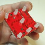
Before soldering, I also added LEDs, capacitors, and transistors to the PCB
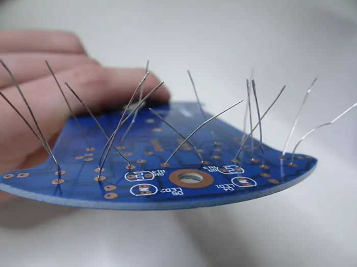
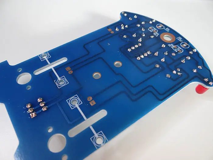
Heat up your soldering iron to about 280 degrees and start soldering.
To make it easier to solder components in the middle, cut legs of the components you’ve already soldered.
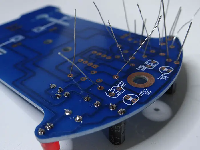
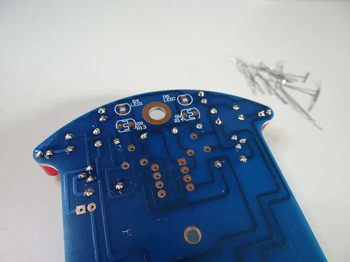
When all of the components are in place you can cut out the rest of the legs.
Now we can mount the switch, potentiometers and the holder socket for the IC on the PCB.
The Legs of those components are so short you don’t have to cut them out when you are done with soldering.
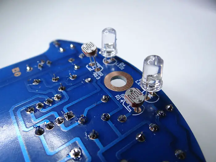
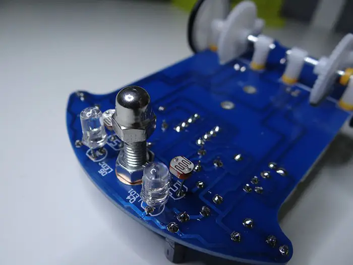
It’s time to mount the last electronic components.
This part is a little bit tricky because you have to solder them on the same side the components are located themselves. These are for line sensing elements.

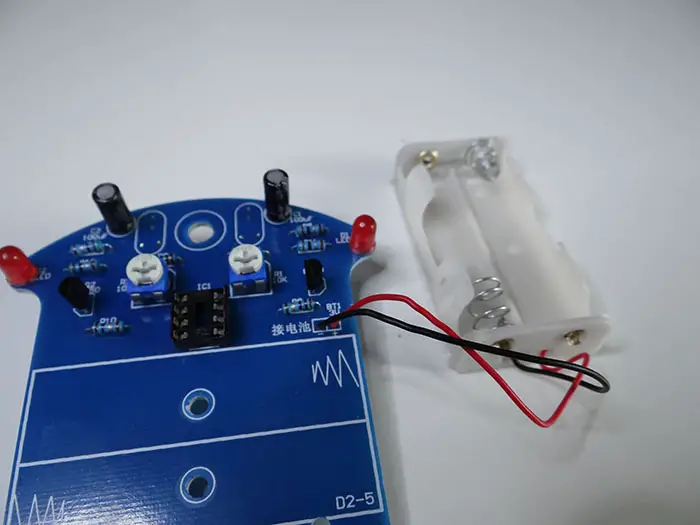
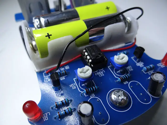
Let’s add the battery holder and stick it to the PCB with a piece of double-sided tape.

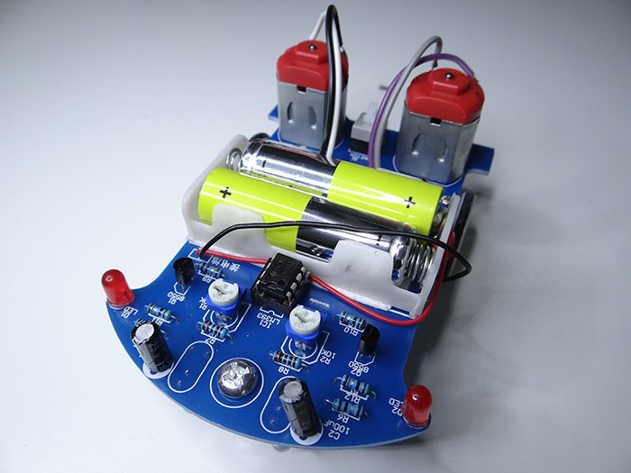
The electrical part of this project is done. It’s time to assemble the mechanical parts.
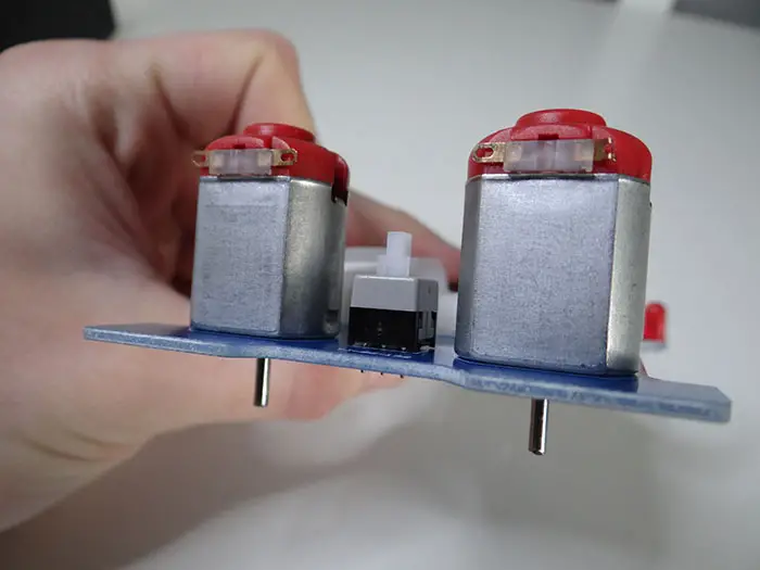
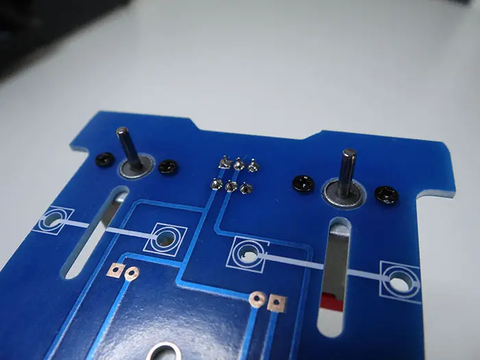
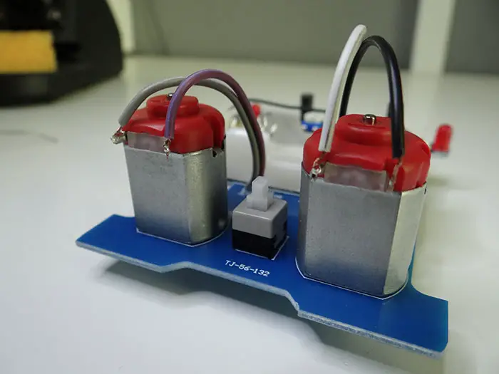
The first thing to do is to fix the motors to the PCB with screws.
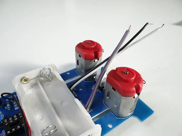
The last thing is to solder cables that connect the motors to the PCB.
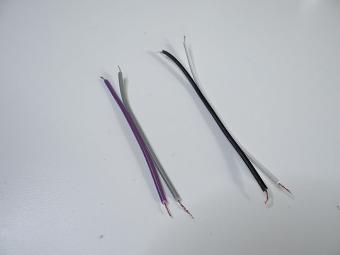
Solder the cables to the PCB and then to the motors.
There are some gears that we have to assemble and fix to the PCB. You have to assemble two exact same elements as shown on the image below.

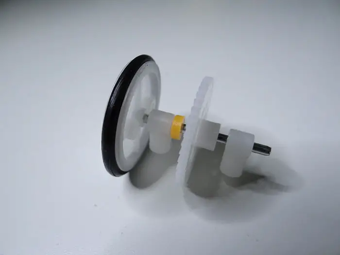
The yellow parts are stoppers meant to prevent mechanical parts from getting loose.
You have to fix those to the PCB, make sure to put those yellow parts on the screw between PCB and plastic part that holds the rod. And don’t forget to put the worm gear on the shaft of the motor.
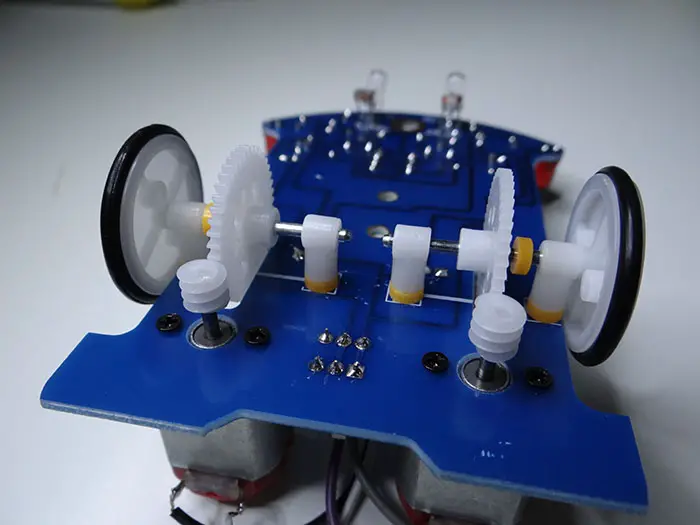
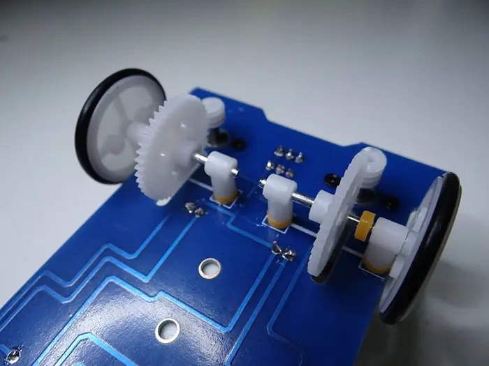
On the front of the robot, you should put the screw with two nuts.
Don’t forget to place the IC in its socket.
And that’s it for this project.
Related posts:
 11 Programmable Robot Toys for Kids
 Electronic Project for Beginners: Fiber Light
 Electronic DIY Metal Detector Project
 Electronic Project for Beginners: Square Wave Generator
 Electronic DIY Project: Building Your Own Oscilloscope
 Electronic DIY Project for Your Lover
 The Different Types of Circuit Boards And What You Should Know
 Electronic Project: The Making of an Electronic Dice