No game defined hand-held gaming in the 80s’ like Tetris. If you every burnt through tens of AA batteries to move through level 1 to 20, you definitely know what I am talking about. And as retro gaming makes a comeback, now is the perfect time to revisit past joys by developing a Tetris hand-held game. To help you recreate this process, the tools and kits I will use here, will be highlighted and their uses explained.
The different steps to take with this pet project will also be outlined and explained in details. At the end of these seven DIY steps, you will have a game that can transport you back to the good old days!
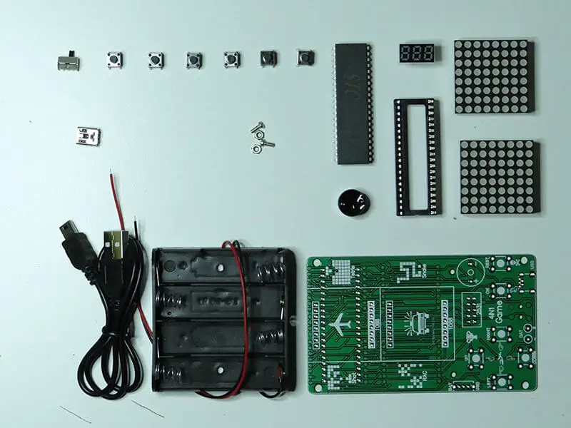
The Components
- A microcontroller – The microcontroller is basically the brain behind the functions of the Tetris. The microcontroller is a small computer on a single integrated circuit.
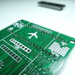
- A PCB – The PCB serves as the mechanical support that connects all the electronic components to be used.
- Sockets –These are supporting and securing fixtures that will hold our project today.
- Switches – These will serve as the buttons for the Tetris game. Each switch will be assigned a control function for continuous use.
- Buzzers – The buzzer is the component responsible for producing the audio the Tetris game will emit.
- LED Displays – These components are responsible for displaying the gaming activities of the Tetris.
- A Power Source – Battery components or a USB socket can be integrated into your project to provide the power the Tetris requires to function.
- A soldering kit
Developing a Tetris Hand-Held Game
Now you have all the components needed in place, we can now start on the building phase. To further simplify the process in each stage, pictures have been attached to assist you in your task. In terms of the effort you will need to put in, the difficulty level is firmly placed at ‘easy’.
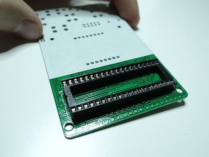
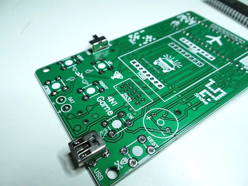
Step 1 – The first phase of the DIY project is soldering the socket for the microprocessor. The sockets are easy to solder and the process will not affect the microprocessor in any way. You must ensure that the alignment used places the notch on the socket and the notch on the solder mask are properly aligned. The alignment can be seen in the image below.
Step 2 – The next step is soldering the USB socket and switch in place. The USB socket will help you power the game. It is important to accurately solder the small pins of the USB onto the PCB. Ensure there are no shorts before moving to the next step.
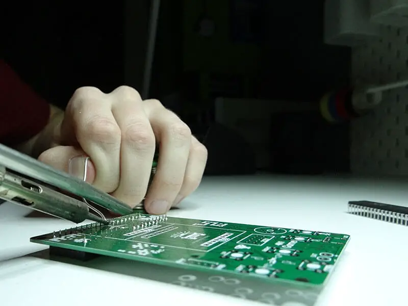
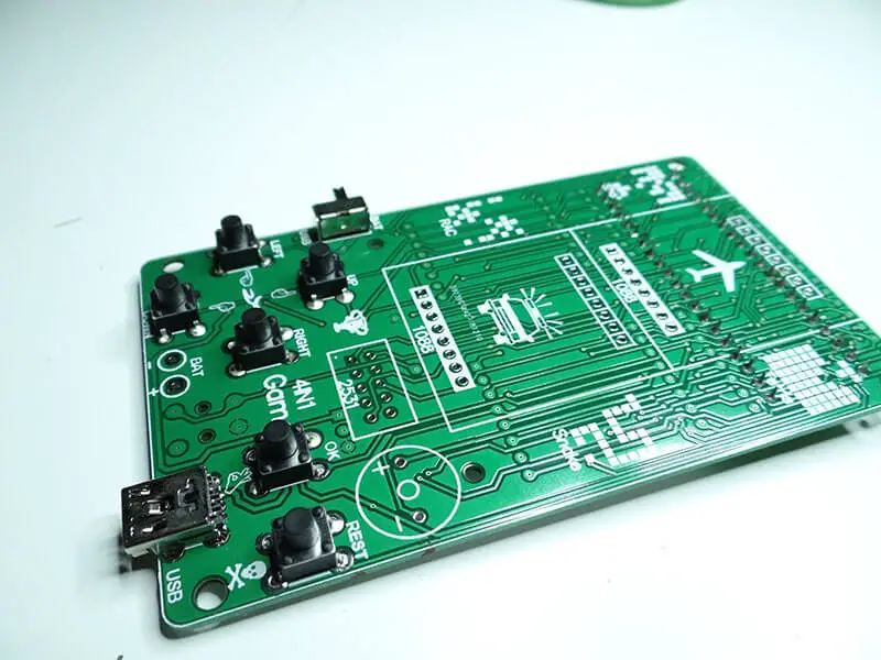
Step 3 – Solder the switches into their places with care. It is recommended that you solder the switches one after the other using the correct configuration. This ensures they stick and don’t fall of the PCB later.
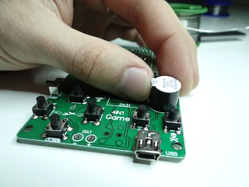
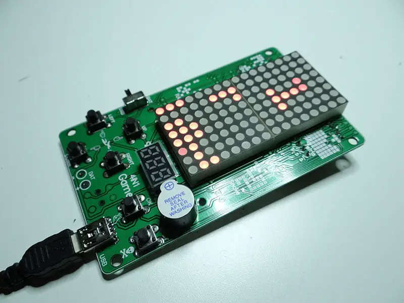
Step 4 – Place the buzzer accurately on the PCB. To do this, simply follow the orientation instructions pasted on the buzzer. This means the ’+’ sign should face upwards as seen in the image below.
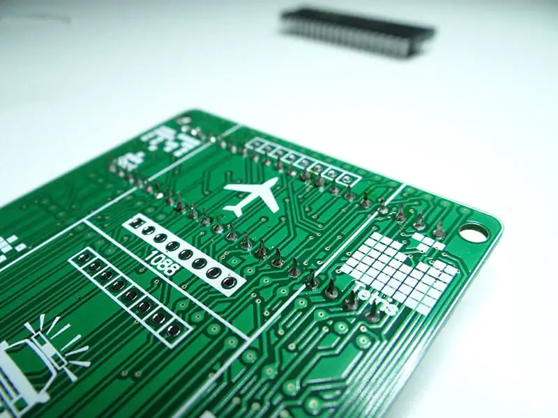
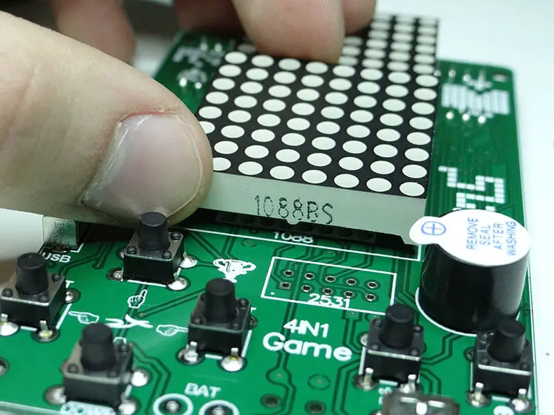
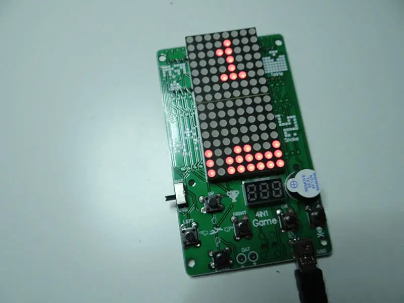
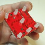
Step 5 – Now, you can solder the LED displays in place. You should start with the bigger displays, also known as, the matrix displays. Once this task is done, you can then move to the smaller display.
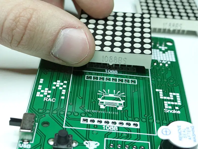
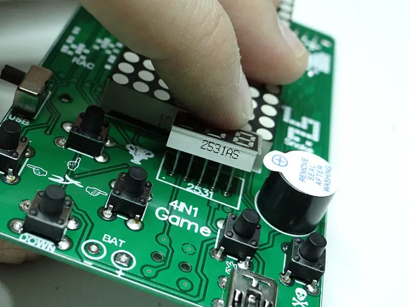
Step 6 – Solder the smaller display in place. This display highlights or shows the scores a player attains during gameplay. Below is a picture of how and where the smaller display should be placed.
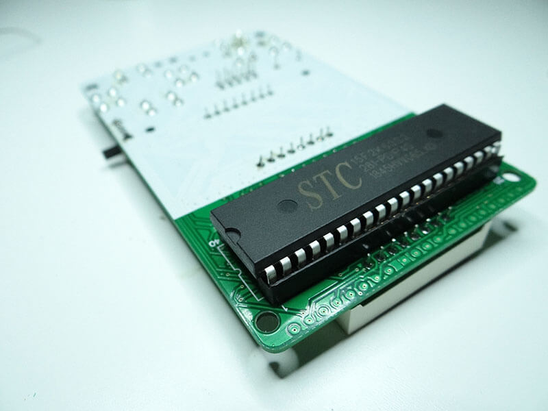
Step 7 – The final task to execute is putting your microcontroller in place. This last piece of the puzzle completes the DIY project and you can finally get started with gameplay. Below, is an image of the microcontroller being placed in its socket in order to complete the building process.
Now that you have all your components in place, the next step is reacquainting yourself with the game of Tetris. You can power the game by plugging in a USB cord into the provided port and you are good to go!
Related posts:
 11 Programmable Robot Toys for Kids
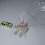 Electronic Project for Beginners: Fiber Light
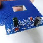 Electronic DIY Metal Detector Project
 Electronic DIY Project: Building Your Own Oscilloscope
 Electronic DIY Project for Your Lover
 The Different Types of Circuit Boards And What You Should Know
 Electronic Project: The Making of an Electronic Dice
 Capacitor Code And Values