Today, we are going to build a DIY metal detector with the help of these devices which will help make the process easy and fun. The end product, the metal detector itself once built can help you find metallic stuff under the ground, who knows what might just be buried there waiting for you!
Here are the items included in the Box:
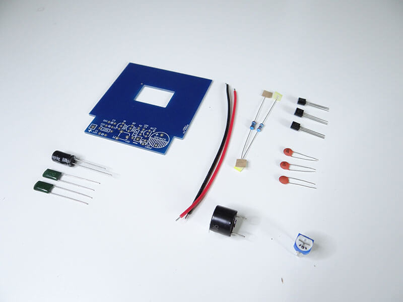
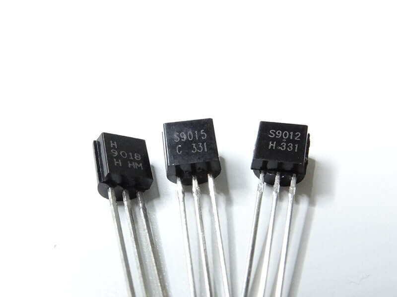
There are components like transistors and resistors which can look identical though there are not.
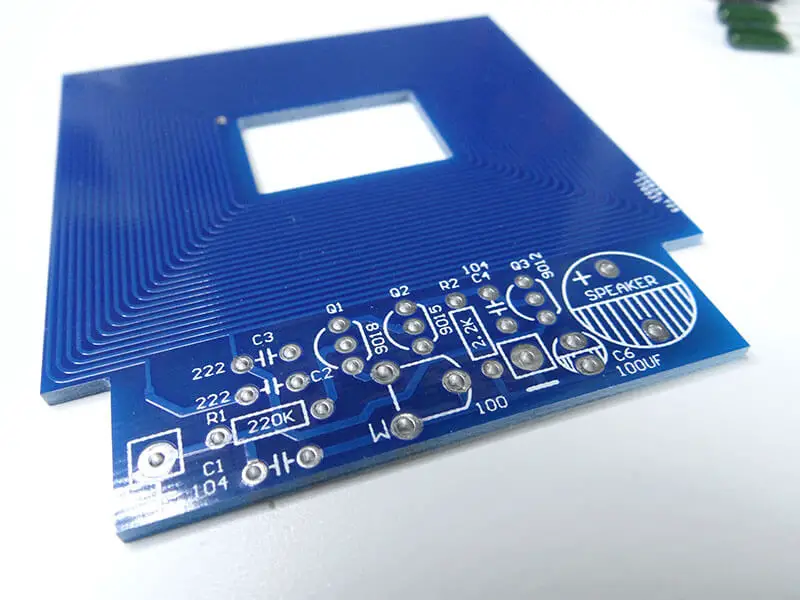
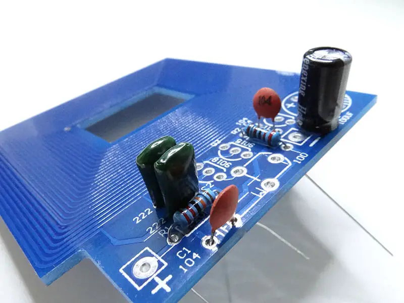
Fortunately enough, everything is labeled on the PCB. We should not have any issue with the assembly of this kit.
Let’s start with all of the capacitors, those are of orange, big black, and green color. Make sure that polarities of the biggest black capacitor match with PCB.
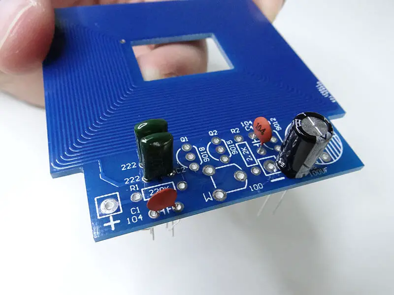
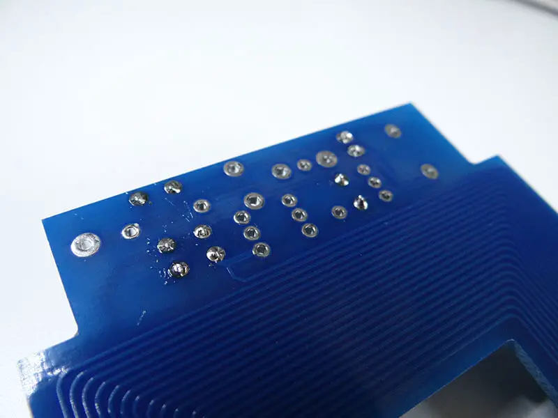
Solder everything and cut out the legs of each component.
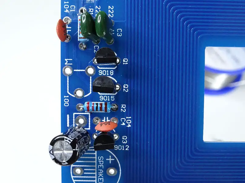
Now we have to put the two resistors in place, each of them has a different value one is 2.2k and the other is 220k. You can measure that with a multimeter. If you don’t have a multimeter make sure that it looks the same as on the image below. (You can learn how to use a multimeter here)
Solder everything and cut off the legs of both resistors.
Now we have three transistors. They are different from one another, we have a 9018, 9015 and 9012. There are labels on the PCB with exactly the same way. Simply put them in their proper place on the board.
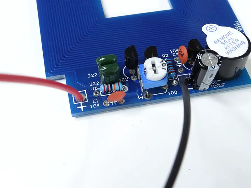
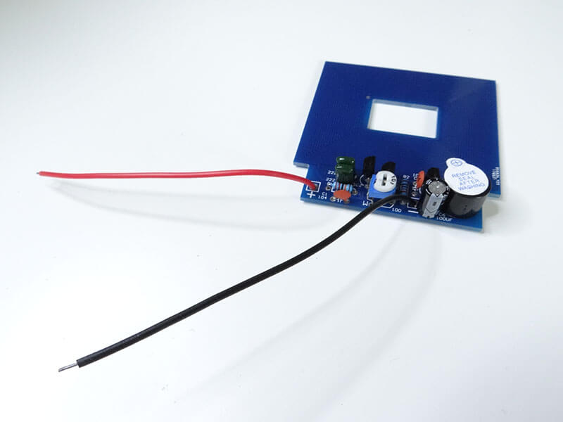
In the end, we can solder the potentiometer, buzzer, and 2 cables.
Make sure that the positive pin of the buzzer is where there is + on the PCB. The holes for power cables are labeled with + and -.
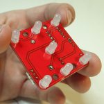
And here you go!
To power it up, you can use anything in the range of 3 to 5V. I am using my adjustable power supply with the voltage adjusted to 4V.
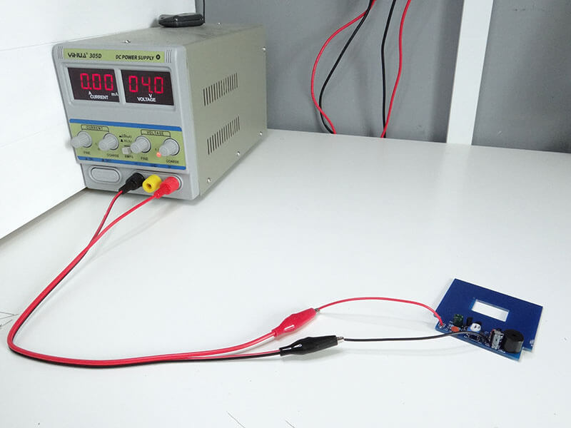
You can also use normal AA or AAA batteries and use it remotely to find some treasures outside if you are into this kind of thing.
Related posts:
 11 Programmable Robot Toys for Kids
 Electronic Project for Beginners: Fiber Light
 Electronic Project for Beginners: Square Wave Generator
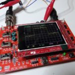 Electronic DIY Project: Building Your Own Oscilloscope
 Electronic DIY Project for Your Lover
 DIY Electronic Fidget Spinner
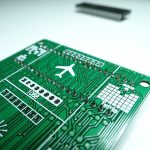 The Different Types of Circuit Boards And What You Should Know
 Electronic Project: The Making of an Electronic Dice
wow, that’s amazingly wonderful article about electronic DIY Metal detector, thanks for sharing with us!