SIMPLE is always the best when you are learning. Talking of simple, today, we are building something impressive using this beginner DIY kit.
This kit will actually help a lot in sharpening your soldering skill and will also help you understand electronic better.
Should I say this project is a great one for beginner and can additionally help show your love to a loved one?
Without further due, Let’s get started!
This quick video will help you have a birth eye view of what this project is about.
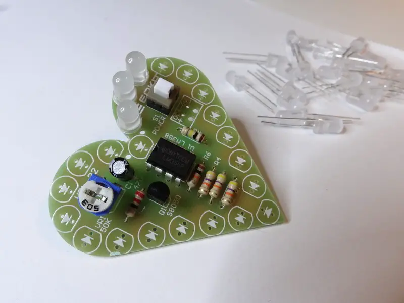
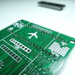
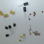
Here are all the component we are going to use.
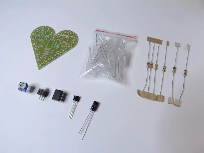
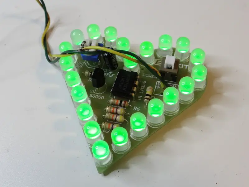
There are four different values of resistors here. I will invite you to make use of a multimeter to find the value of each while soldering it on the board. You can also check the third image below, and place your resistors as shown on the image.
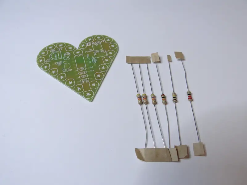
Solder all the resistors and then cut out their leads.
You should always cut out the leads of the components when they are too long after soldering, that will help avoid potential shorts.

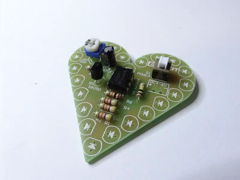
Next two things to solder are: the potentiometer and the switch. With this potentiometer we can control the frequency of the LEDs blink and the switch is there to turn the device ON and OFF.
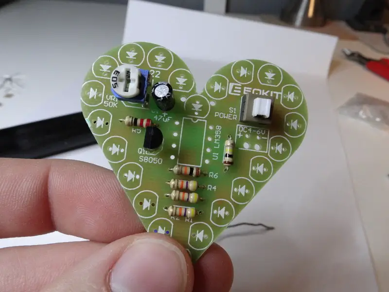
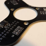
And finally the IC (Integrated Circuit) right in the center of the PCB.
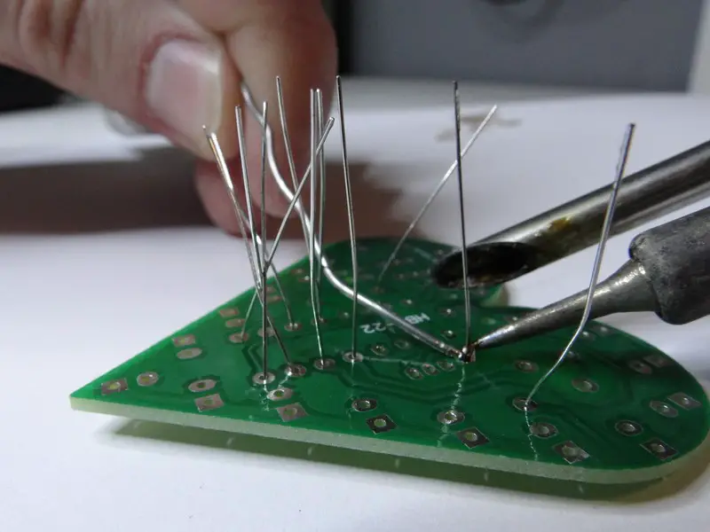
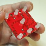
Time to solder all of the LEDs on the edge of the PCB. There are 23 LEDs to solder but I found 26 LEDs in the kit so there are 3 spare LEDs. Make sure to solder them properly. Remember the longer lead of the LED is the positive one.
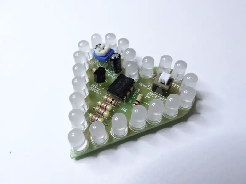
My advice is to solder 2 to 3 LEDs at once, it simpler to keep them straight that way.
You can also cut out the leads after each step so to make you have more space to solder the rest.
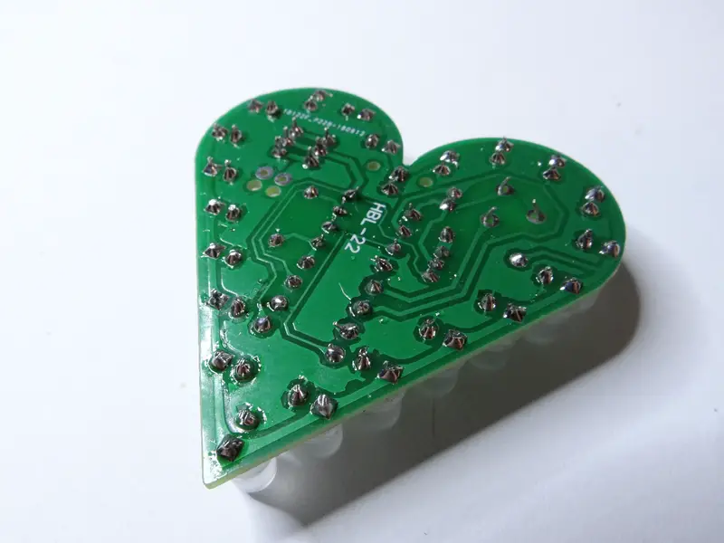
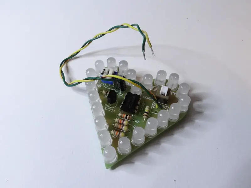
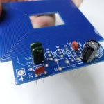
Here is how it should look like with all the components in place. This is the other side of the PCB.
Last thing that we have to do is to solder a cable that will help us connect to power. Unfortunately this cable isn’t provided with the kit so you have to find two pieces of wire by yourself.
To power it you can use 4V up to 6V, I will use my lab bench power supply for that.
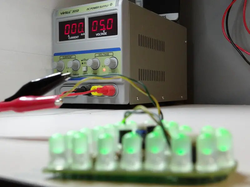
And voila!
Electronic DIY projects:
- Electronic DIY Metal Detector Project
- Electronic DIY Voice Control LED Project
- Electronic Project for Beginners: Square Wave Generator
- Capacitor Code And Values
- Best PCB Design Software for Electrical Engineers
- Reasons Why You Should Use PCBWay for Your Next PCB Project
- DIY Electronic Fidget Spinner
- Understanding the Basics of Printed Circuit Boards: The Designing, Components, and Construction
- Electronic Project for Beginners: Fiber Light
- The Uses and Benefits of Circuit Board Holders
- Electronic DIY Project: Building Your Own Oscilloscope
- Electronic Project: DIY Audio Level Indicator
- Creating Your Very Own DIY Spectrum Analyzer in 9 Easy Steps
- Electronic Project: DIY LED Emergency Light
- Arduino LED Cube Project
- Electronic Project: The Making of an Electronic Dice
- How to Clean a Circuit Board
- Top 15 Engineering Books that Simplify Technical Terms
- Robot Building Kit for Education
- Electronic Project: DIY Electronic Clock
- Solar Robotics: The OWI 14-in-1
- Tetris: Pursuing a Nostalgic DIY Project
- Electronic DIY Project for Your Lover
- Electronic Project: DIY Line Follower Robot
- Electronic Project: DIY Advanced clock
- The 10 Steps to Making Your Personal DIY OLED Wrist Watch
- The Different Types of Circuit Boards And What You Should Know
- Electronic DIY Night Lamp
- The Most Entertaining and Programmable Robot Kits for Adults
- 11 Programmable Robot Toys for Kids
- Top 9 Books Every Engineer Should Read
Related posts:
 11 Programmable Robot Toys for Kids
 Electronic Project for Beginners: Fiber Light
 Electronic DIY Metal Detector Project
 Electronic DIY Project: Building Your Own Oscilloscope
 DIY Electronic Fidget Spinner
 The Different Types of Circuit Boards And What You Should Know
 Electronic Project: The Making of an Electronic Dice
 Capacitor Code And Values