We’ve recently written an in dept Draftsight review here, compared AutoCAD and Draftsight and even had a quick CAD exercise using Draftsight to help you have a glimpse of what it feels like when working with Draftsight. Today, we are bringing the 10 tips you should learn to start drafting using Draftsight.
Draftsight is a free, simple CAD program that loads fast compared to other CAD software like AutoCAD making it one of the nicest alternative I do recommend for beginners.
Without further delay, let’s dive into it
Start using Draftsight in 10 simple steps
1. Cartesian coordinate system
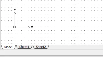
The drawing space can be thought of as a 2D planes (while drawing in 2D) where every location has unique coordinates with the form (x,y). This concept is similar to the Cartesian Coordinate System in AutoCAD explained here.
If you are working on a project where precision is needed, this will be of a help. Although this become unimportant for most advanced projects, it is necessary you have understood this concept while working with any CAD program, Draftsight included.
2. Toolbars
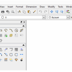
Toolbars help access tools that will help you get your project completed. In the current version of Draftsight, all toolbars are not displayed by default. You can add then as needed and place it/them where you judge convenient for you.
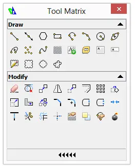
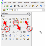
Here is the toolbox Tool Matrix where you will find all the Draw and Modify tools.
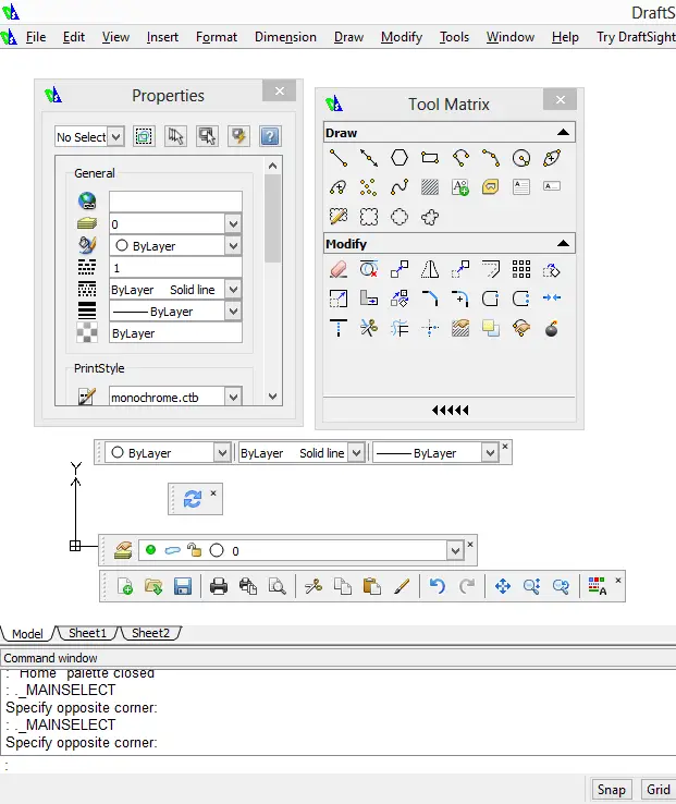
Here is an attempt to mess around with the position of some toolboxes and toolbars for the sake of letting you see you can really customize the look of the program to you likeness.
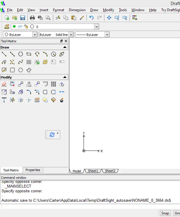
And here is how it looks when in order.
To Add a toolbar
- Right click on an empty space on the menu-bar
- Select Toobars
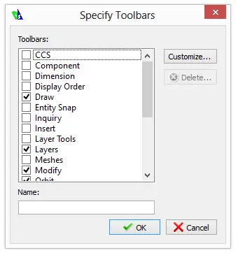
- Activate the wanted toolbar
When you right click, you will see the following
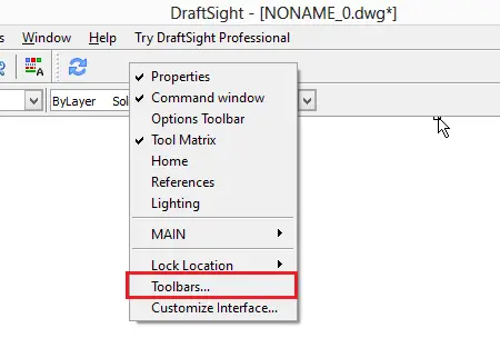
Click on Toolbars, and you can activate the toolbar(s) you want to add.
3. Command line input
The command line input is the small window below the drawing windows.
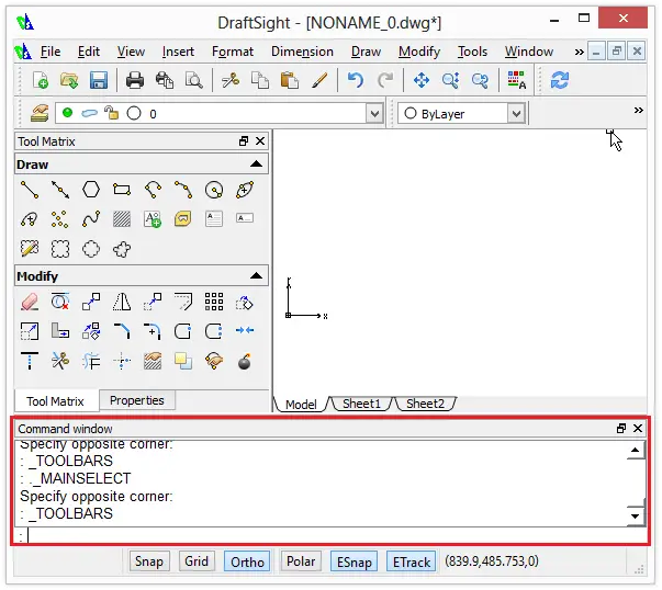
The command line input allows to interact with the program.
Here is is a simple example.
Typing LINE in the command line input and Pressing Enter allows to activate the line tool that allows to draw a line.
For some commands, you still need to provide intermediary information to really have the CAD program do what you really need to, and the command line is often the indicated means you can use to do this. Still confusing right!? feel free to check this post about commands in AutoCAD.
4. Wheel-mouse pan & zoom
The mouse is the most used input means you will ever use to communicate with the program. Make sure the computer mouse you use has at least 2 buttons (left and right buttons) and the scroll wheel.
In most CAD programs like in Draftsight, the Wheel is used to pan and zoom. Scroll the wheel forward or backward allows to zoom out and in respectively and Clicking the wheel, holding and dragging allows to pan.
5. Command aliases
Most command have aliases or short names (or keyboard shortcuts). For example, the LINE command has as aliases L, meaning, if I want to activate the LINE command via the command line input, writing L and Pressing Enter is similar to writing LINE and Pressing Enter.
Some common used aliases are:
- C for CIRCLE
- L for LINE
- A for ARC
- N for NOTE
- TR for TRIM
- EX for EXTEND
- IL for INFINITELINE
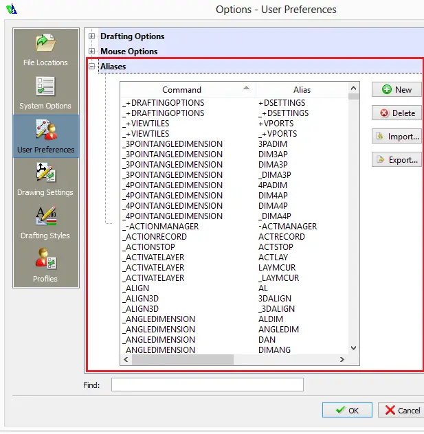
You can find the full list of command and their aliases with a right click in the drawing area
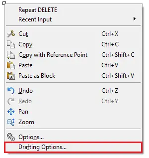
Click on Drafting Options, under User Preferences, You will find Aliases
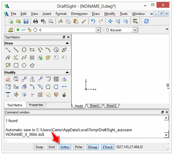
6. ORTHO mode
The ORTHO mode assures your are keeping it straight so to say, When it is activated, your mouse are restricted to only vertical and horizontal directions when using a command. This is needed when drawing an horizontal or vertical line, or when you are moving an object, and need to make sure you are moving it 7 units to the right for example.
7. Dimensions and units
Remember the command line input we talked about few second ago? it helps you enter the exact dimension of the object you are drawing. Let’s create an horizontal line of 10 units to illustrate this
- Click on the LINE icon in the Tool Matrix and Press ENTER
- Click in the drawing window to specify the first point of the line
- Drag you mouse left or right while the ORTHO mode is activated
- Enter the dimension of the line in the command line input and press ENTER
As you can see, you are able to draw object with really accurate dimensions.
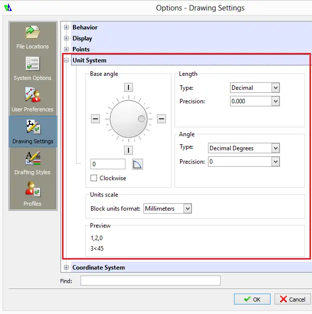
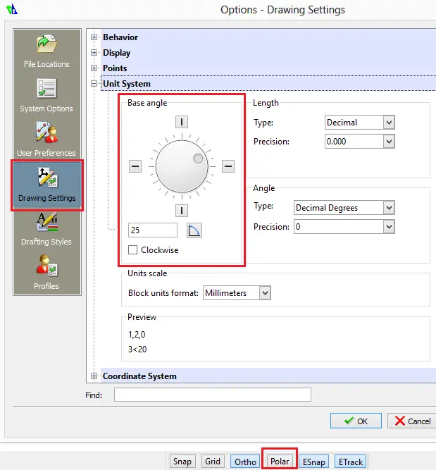
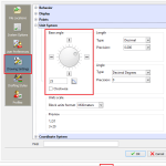
As for units, you can define the unit of your drawings under Drawing settings, Units systems
8. Lines
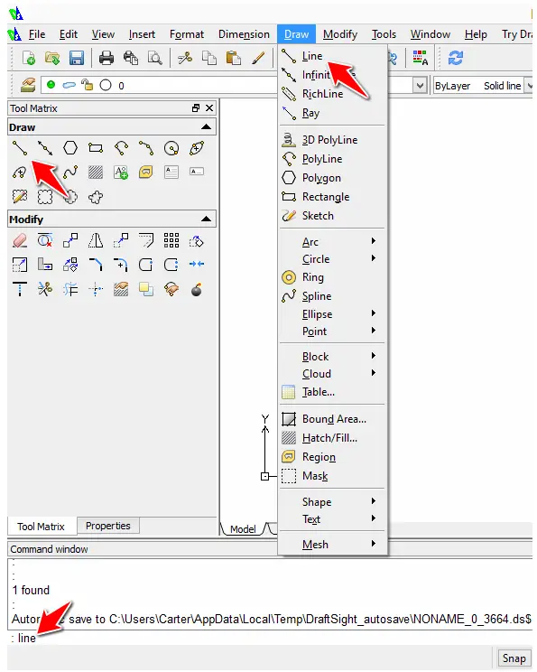
Before diving into creating with Draftsight, I will show you many way you can activate the LINE command just for you to get your head around this command.
To activate the LINE command you can use one of the following
- Type LINE in the command line input and Press ENTER
- Click on the LINE icon on the Tool Matrix
- Click on the Menu draw, and select Line
Now, creating a line with Draftsight happen the exact way it happens while working with AutoCAD. I will invite you to check these posts where we had fun explaining how the LINE command works.
Mastering the LINE command in AutoCAD
Angles and lines in AutoCAD
Some differences, can be about the way you restrict the mouse to help you identify specific angle while drawing. If in my Drawing settings, I fix the Base angle to be 45 for example, and activate the Polar tracking while drawing, Draftsight will help me know every time I hit the 45 or any multiple of 45 degrees angle.
9. ESnap
ESnap stands for EntitySnaps
ESnap (you can see its location on the image above, near the Polar button) allows to start and/or end at a specific location on an already created element. Say, I want to start a new line in the middle of an already created line, ESnap helps it provided it is activated.
You can personalize the behavior of this mode with a right click on its button and a Click on settings.

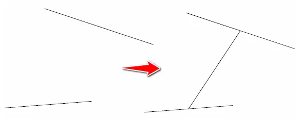
Example:
If it is needed to draw a line starting and ending at the center points of both segment, ESnap need to be activated and its option Midpoint need to be ticked (You can locate the Midpoint option in the screen shoot above)
10. Grid
Grid displays points all over the drawing window, if both Grid and Snap are activated, and I activate the LINE command: the cursor movement will be dictated by those points.
Final words
And there you have it! This almost sums it all. If you want to try some exercises using this simple CAD program, you can check these ones.


is there way to convert .dwg files to pdf format using bash terminal and not by tool’s GUI ?
Not to my knowledge. The only way is to use the GUI as far as I know.