The present challenge is one of a kind. It is good to know that the objective is not only to be able to use AutoCAD commands but also to learn tricks and combine all the commands to get to the final image.
And one thing I will never mention enough is, there are often many ways to achieve a thing in AutoCAD. Use the idea that comes to you first if it does the job.
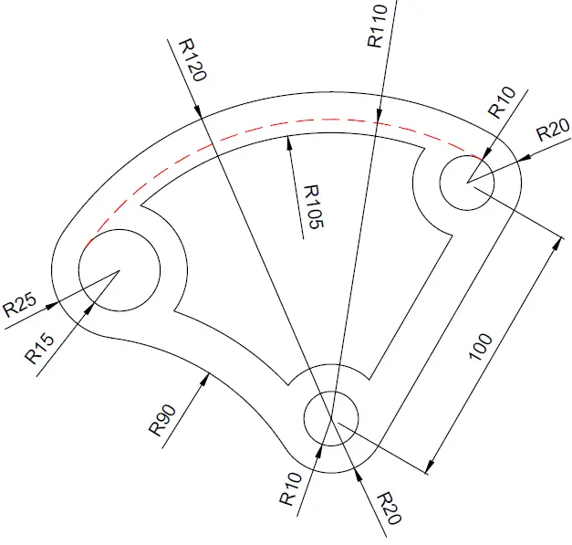
Simply remember to check your dimensions at the end of the exercise and make sure they match the ones mentioned in the image-exercise.
We will look a little deeper into the OFFSET command today. It is needed.
OFFSET command in AutoCAD
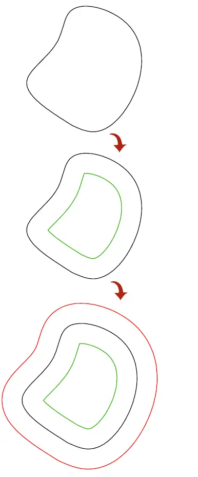
The OFFSET command helps create parallel lines and parallel curves.
If you have an object and want a similar parallel object to it, this command will be helpful.
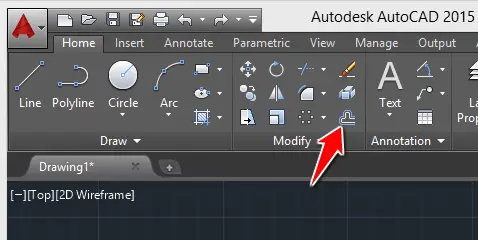
To use the OFFSET command
- Click on the OFFSET icon
- Specify the OFFSET distance and Press Enter
- Select object to OFFSET
- Specify a point on side to OFFSET
Learning AutoCAD Basics
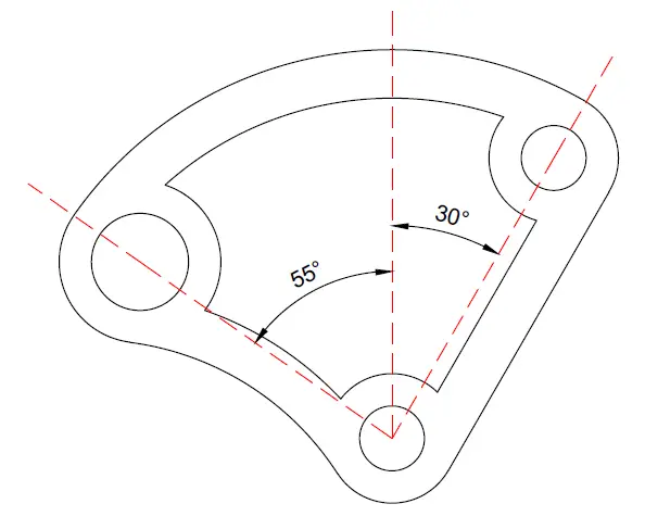
The use of the ROTATE command will be required in this exercise, as well as the OFFSET command.
Below you will find diverse dimensions to help the replication of this session’s task.
Figure 1
Figure 2
Execution
You need to start from the outer part of the object.
After getting the above figure done, OFFSET all circles with 10 units inwards, and OFFSET all line with 15 units inwards.
And you should end up here.
All you need to use the TRIM command and the FILLET command to get all done.

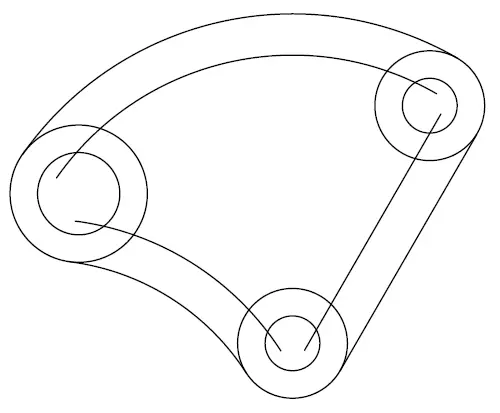


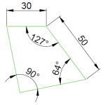
To get the image above, You do not need to use the tan tan radius command. Just get those lines and the big circle created. Use the information provided in the exercise. Then you have two intersecting points between the lines and the circle to draw the circles as shown the exercises. You will need to use the tan tan radius only once in this exercise, and you can even complete the whole exercise without using it.
alright, i tried to sort it out, and what i get is this:
the distance between upper left circles and lower circle is NOT the same as upper right and lower circle (100 unit). I drew the upper left using “two end points” method by setting D=50 along the line. Here is what I have drawn. Thank you very much your help ^^ https://uploads.disquscdn.com/images/828252f147dd2615c4db93d26639f844f8836a3ff471981a452e485d60a09f1a.png
it looks fine.
Remember you can always download this exercise dwg file Here.