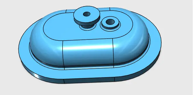
We have recently worked on designing this 3D model using AutoDesk 123D Design here. Today, we are coming back at it, but this time we are going to be using Solidworks. You are just about to learn how to create a simple 3D sketch using Solidworks.
In 3D sketching, a graphical space handle helps maintain your orientation while you sketch on several planes.
Let’s take a look at how we can use 3D sketching command in SolidWorks using this exercise.
Without further due, let get into it
Solidworks 3D sketch
Step 1
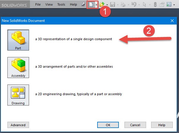
As usual, start with creating a New Part
Step 2
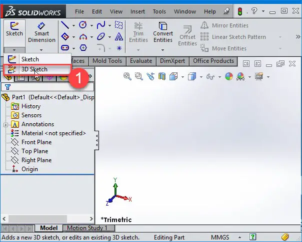
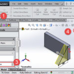
Click on 3D Sketch Tool_3D_Sketch (Sketch toolbar) or Insert 3D Sketch to open a 3D sketch on the top plane in Isometric view.
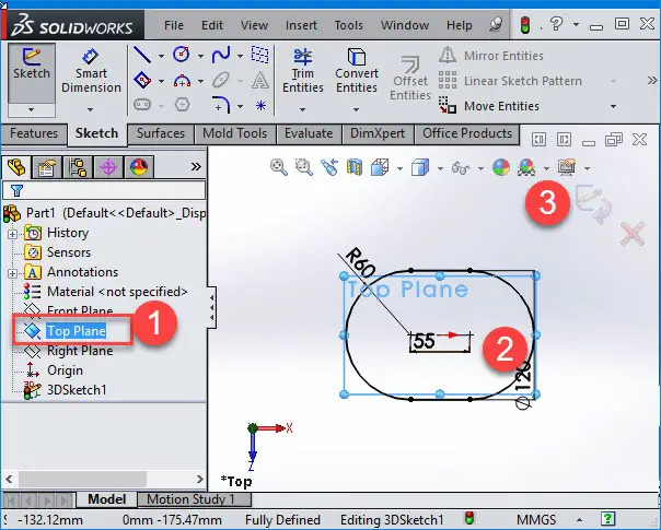
Step 3
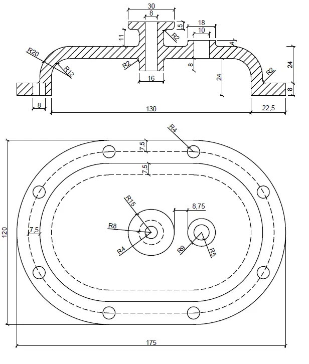
Select the Top Plane and select Normal to view. Draw the following object.
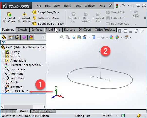
Step 4
In 3D sketching in solidwork, we need to give a direction to the Extrude. Therefore, we need to create a line to be able to use it for the extrusion.
First, close the first 3D sketch, create a new one, select the front plane and draw a line.
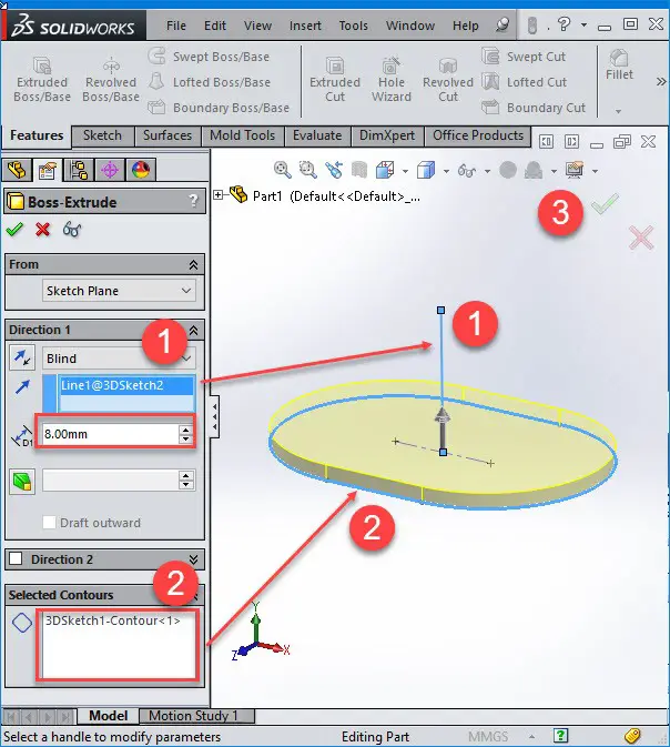
Step 5
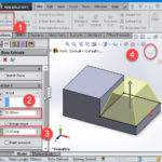
Choose Extruded Boss/Base, give 20 mm as thickness, select the line that we’ve created in the previous step.
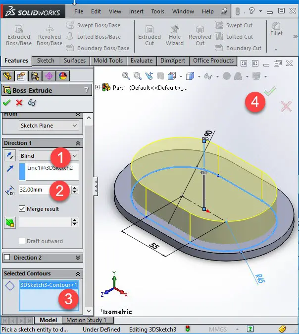
Step 6
Create the additional part as shown on the image below. The Extrusion length is 32 mm.
Step 7
Make another sketch with 3D sketching but this time use extrude cut to create a hollow.
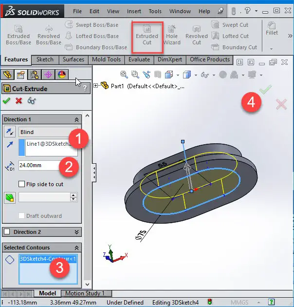
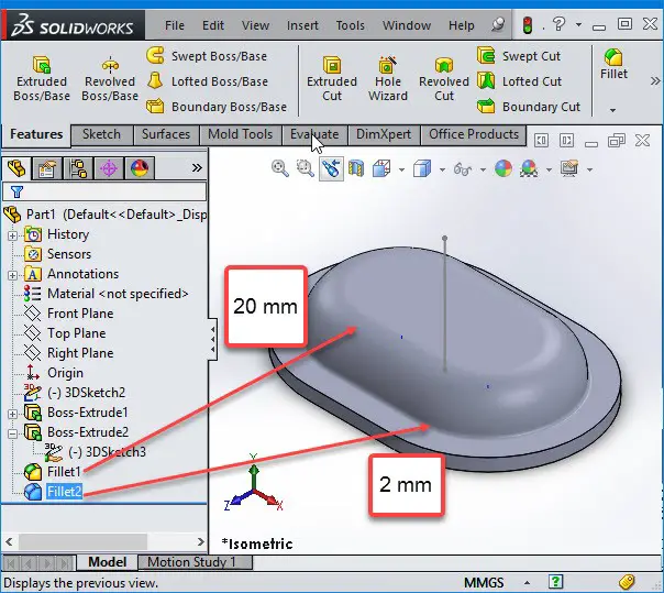
Step 8
FILLET the upper edge by 20 and the flat edge by 2.
Step 9
In solidwork we cannot use the Revolve command in 3D sketching as we want to draw everything with 3D sketching. I am going to use two Extrudes to create the desired shapes.
To make a 3D sketch on a specific surface, click on the surface then go to sketch and select 3D Sketch On Plane.
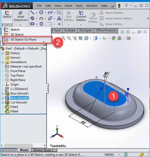
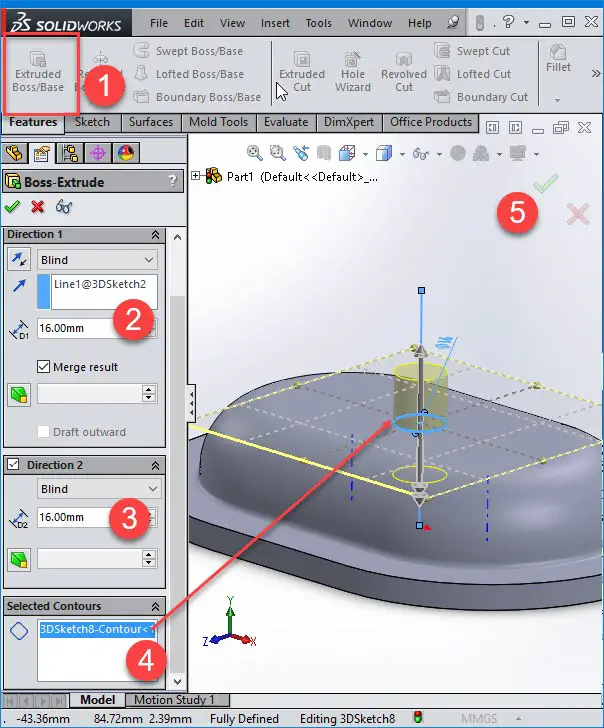
Step 10
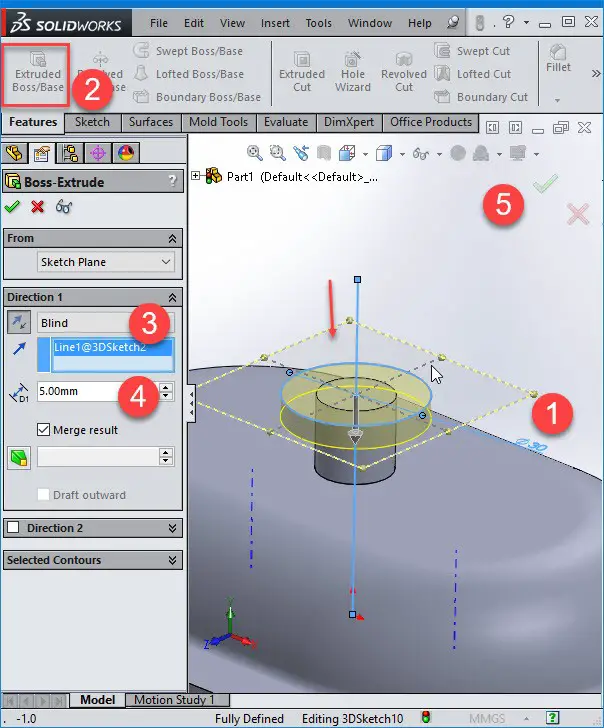
Make a circle with a diameter equal to 6 mm and extrude by 16mm upward and downward.
Step 11
Make another circle using the same method but this time with diameter set to 30 mm and an extrude of 5 mm.
Step 12
Now, we are going to make hole. Once more, make a 3D sketch and draw a circle of 8 mm in diameter, use Through All to Extrude cut.
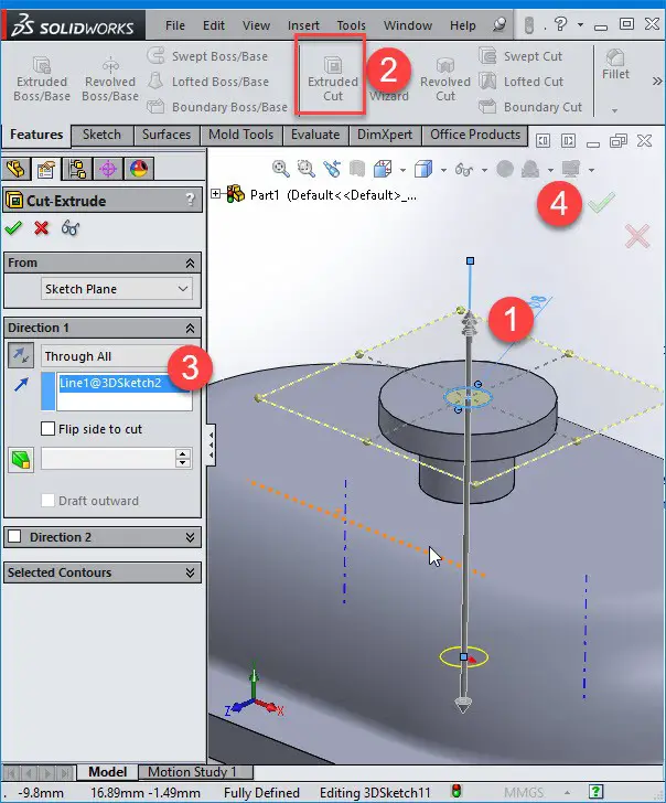
Step 13
Do the same to create the other part of the design
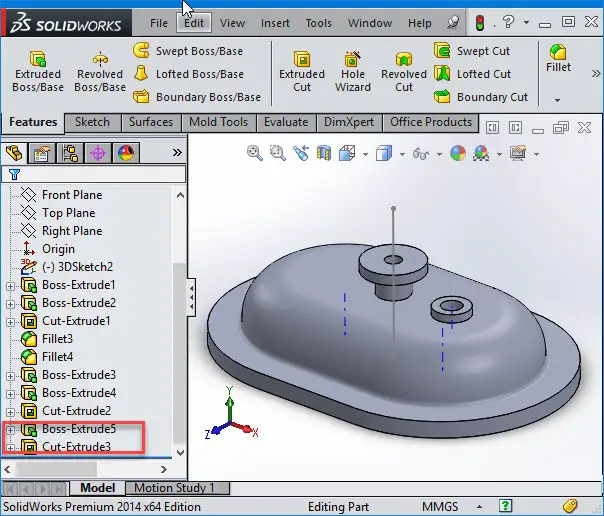
Step 14
FILLET the necessary parts of the object to complete the project.
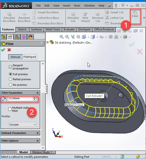
As we have seen with this one, when sketching in 3D, you can snap to the major directions, X, Y, or Z, and constraints are applied Along with X, Y, and Z, respectively. When sketching on a plane, you can snap to the horizontal or vertical directions in the plane.
You might also like:
- Solidworks Equation
- Solidworks Tutorial: Sheet Metal
- How to Create a Sphere in Solidworks
- SolidWorks Tutorial: Extrude
- Solidworks Tutorial: Assembly
- Solidworks Tutorial: Cosmetic Thread
- Solidworks Tutorial: How to Draw a Coke Bottle
- Solidworks Tutorial: Easy to Follow 3D Sketching Using Solidworks
- Solidworks Tutorial: Convert Entities
- SolidWorks Tutorial: SWEEP
Related posts:
 Solidworks Tutorial: Circular Pattern
 Solidworks Tutorial: How to Mirror Parts
 AutoCAD vs SolidWorks – Which One Is The Best?
 Solidworks Tutorial: Convert Entities
 Scrutinizing CATIA vs SolidWorks
 7 Free Alternatives to SolidWorks Every Student Should Know
 Comparing Pro Engineer vs SolidWorks
 The Best Graphics Card For SolidWorks