SWEEP is the one feature in Solidworks that helps sweep a closed profile along a closed or open path. In this session, we are going to use a simple 3D object as an exercise to demonstrate the use of the SWEEP command in Solidworks.
Let’s right dive into it.
Solidworks SWEEP

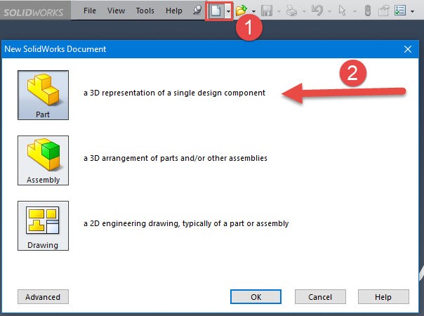
Step 1
Create a New Part
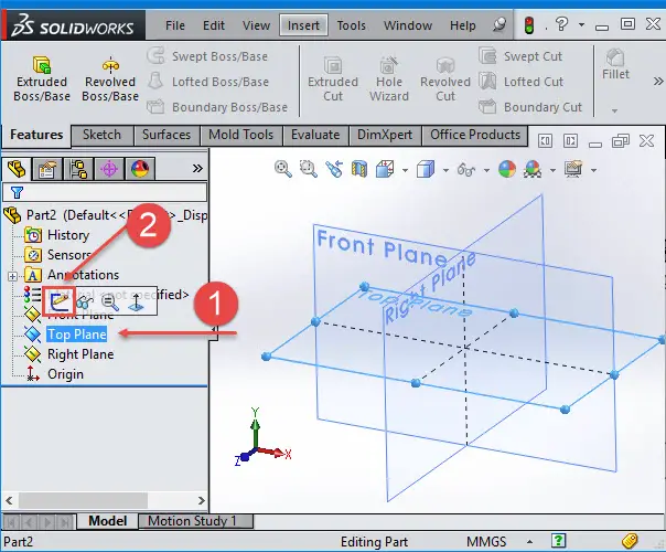
Step 2
We need to select the desired plane. Click on the Top Plane and select Sketch
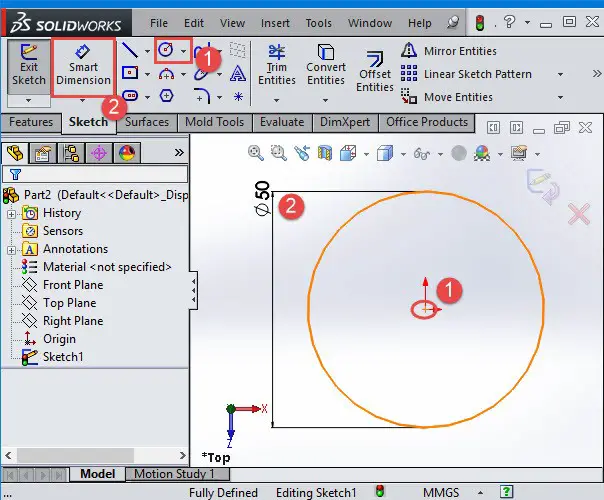
Step 3
Make a circle with the origin of the sketch as the origin of the circle and click on Smart Dimension. Enter 50 mm to specify the diameter of the circle.
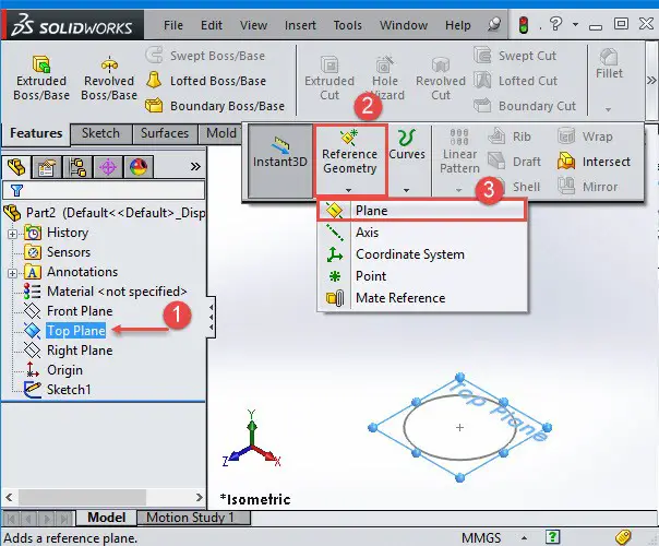
Step 4
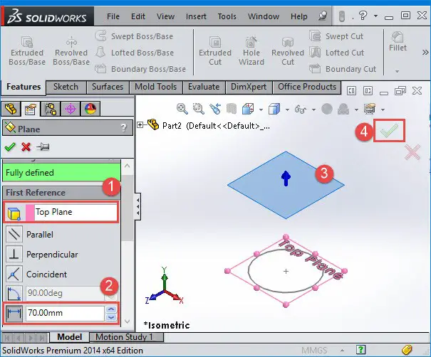
Click on the Top Plane, go to features, select Reference Geometry and select Plane
Step 5
Select the Top Plane to indicate the first Reference and enter 70 mm
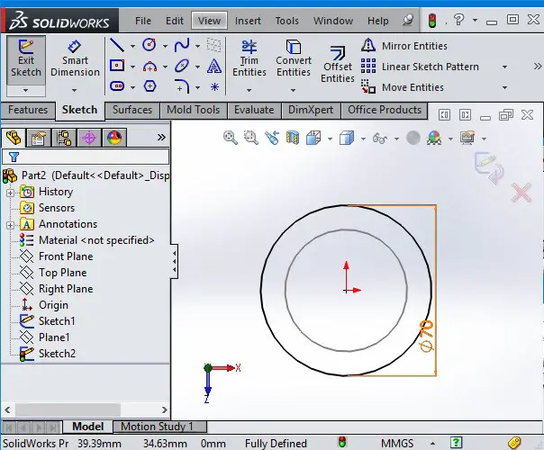
Step 6
After creating plane1, draw a circle with 70 mm as diameter.
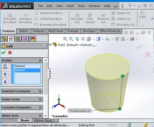
Step 7
Use the LOFT command to come out with the following image.
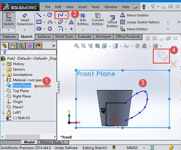
Step 8
Now, we are going to create a Path for the Sweep Extrude command. Select the Front Plane, select Sketch and use the Spline command to draw a Spline as shown on the image below. Thi will serve as a trajectory or path to the SWEEP command.
Step 9
Create another plane but this time, consider the Right Plane as the first reference and the point at the end of the path as the second reference to create a new plane. The path can be open or closed, a set of sketched curves contained in one sketch, a curve, or a set of model edges
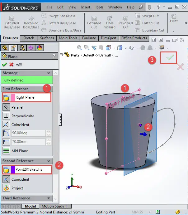
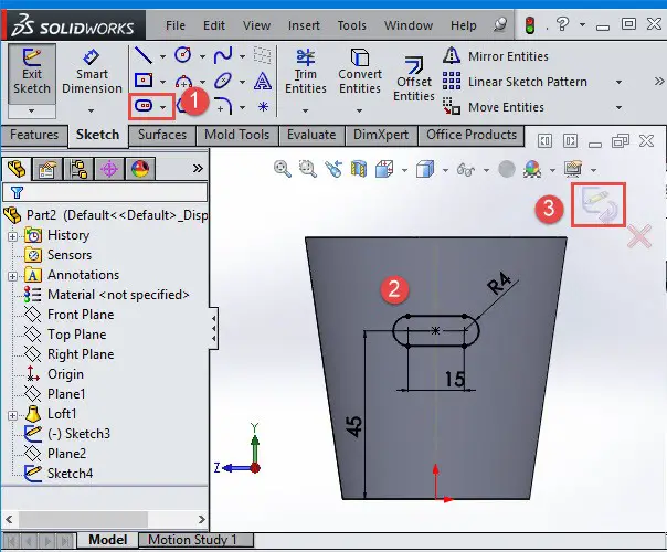
Step 10
Create a sketch on the Plane2, use CenterPoint Straight Slot command to create a profile for sweeping and give the same dimensions as marked on the image below. The profile must be closed for a base or boss sweep feature.
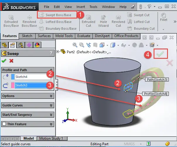
Step 11
If you were to create a spring model, a complex hollow pipe, an air conditioning duct, a curved rod, tubes and twisted parts, this command will be almost inescapable.
To put the final touch to our session, click on Sweep Boss/Base and select the profile and the path following the demo below.
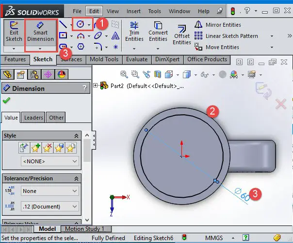
Step 12
Create a sketch on the highlighted surface and draw a circle of 60 mm of diameter.
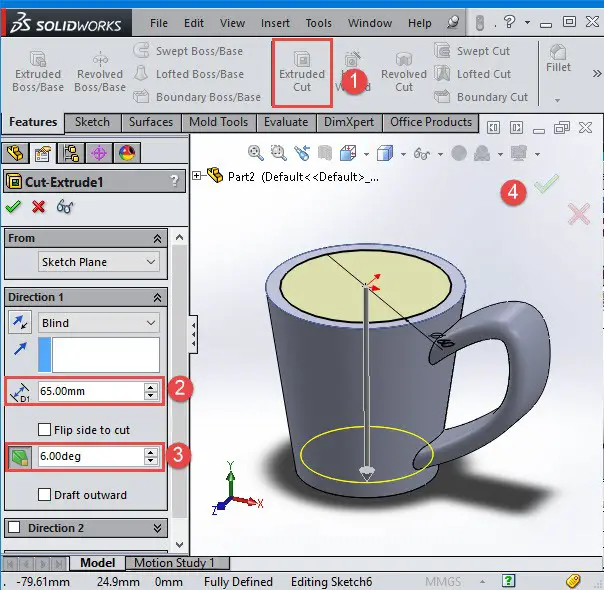
Step 13
Use the Extrude Cut command, give 65 mm and 6 degrees to the depth of the cut and draft the angle accordingly.
Without exaggeration, this command can be placed amongst the 10 most used commands in Solidworks making it a must-know to anyone looking to model using Solidworks.
You might also like:
- Solidworks Equation
- Solidworks Tutorial: Sheet Metal
- How to Create a Sphere in Solidworks
- SolidWorks Tutorial: Extrude
- Solidworks Tutorial: Assembly
- Solidworks Tutorial: Cosmetic Thread
- Solidworks Tutorial: How to Draw a Coke Bottle
- Solidworks Tutorial: Easy to Follow 3D Sketching Using Solidworks
- Solidworks Tutorial: Convert Entities
- SolidWorks Tutorial: SWEEP
Related posts:
 Solidworks Tutorial: Circular Pattern
 Solidworks Tutorial: How to Mirror Parts
 AutoCAD vs SolidWorks – Which One Is The Best?
 Solidworks Tutorial: Convert Entities
 Scrutinizing CATIA vs SolidWorks
 7 Free Alternatives to SolidWorks Every Student Should Know
 Comparing Pro Engineer vs SolidWorks
 The Best Graphics Card For SolidWorks