We have seen a couple of ways you can go to draw a straight line in AutoCAD here. Before diving into today’s tutorial, I would like to mention something I totally forgot to mention in previous sessions.
Many people fall into this trap. You know how you are drawing a straight line in Microsoft Paint, You click and hold, move your cursor, and then when you release the click, you have a straight line? It does not work this way in AutoCAD. In AutoCAD, you actually have to release the click before moving the mouse, and you have to initiate the second click to finish drawing the straight line. Confusing?
Here is what I mean. To draw a straight line in AutoCAD:
- Activate the LINE command
- Click on the starting (Do not hold your click)
- move your mouse
- Click to indicate the ending point (Do not hold the click)
- Press on the ESC key on your keyboard to end the process
There are very very few actions in AutoCAD that force you to click and hold. As for now forget about CLICK AND HOLD. We will cover exceptional cases later.
That being said, let’s Start.
Drawing a Straight line with a dimension in AutoCAD
We need to talk about the ORTHO mode before anything else here.
The ORTHO mode
The ORTHO mode constrains the cursor to horizontal and vertical movement, which helps you draw straight horizontal and straight vertical lines easily.
Every time one needs to draw either a vertical or a horizontal straight line, he/she needs to make sure the ORTHO mode is activated.
The ORTHO icon is located in the Status Bar (Downright corver)
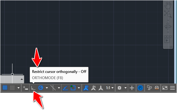
How do you know it is activated or not?
Pay attention to the information box that pops up when you hover over the icon. You can also use color indicators to know, Blue ORTHOMODE icon for ON and White ORTHOMODE icon for OFF.
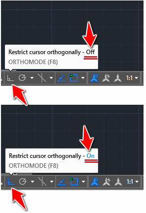
How do you activate the ORTHO mode?
Just click on the icon to toggle it. If it is OFF, it will turn ON and vice versa
Now that we know what ORTHO is and how to use it, we can move forward.
Let’s draw a vertical line of 50 units of length.
To draw a line of 50 units:
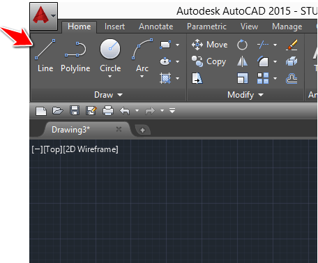
1 – Click on the LINE icon
2 – Click once in the drawing area (Don’t hold your click)
3 – Activate the ORTHO mode if it is not activated
4 – Move the cursor away from the first point in the direction you want the line to have. Since we are drawing a vertical line, you can only go either upward or downward
5 – Type 50 on your keyboard and hit ENTER on your keyboard twice
To draw a horizontal line, just change the direction in step 4 to either left or right.
Practice exercise
Using what you have just learned, you must be able to complete the following exercise.
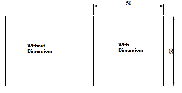
Do not mind the annotation, once we learned how to write a text in AutoCAD, and how to annotate a drawing, you can come back and finish it up. But for now, focus only on drawing 4 lines to make a square.
Polar tracking
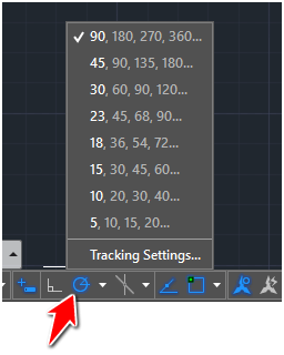
This feature helps track specific angles when you are drawing in AutoCAD. By default, this is set to 90, 180, 270, 360.
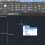
How to access this?
Right-click on the Polar tracking icon like shown on the image below
What can I use this for?
You can use it to draw the following 2D image.
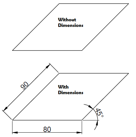
How did we get here?
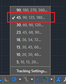
Remember earlier in this article when we used ORTHO? We were only able to draw vertical and horizontal lines, now we can also track direction with specific angles. The process is the same with what we did when drawing the square above, but now we need to set the polar tracking to 45, 90, 135, 180…, draw the baseline as we did with the square, and use the polar tracking to know you are at 45 degrees before drawing the 90 unit line.
You can set these tracking angles to be whatever you want. Using the Tracking settings, you can enter your angle of preference.
These tutorials might be useful:
- Breakline AutoCAD
- Tutorial 20: Convert Line to Polyline
- Tutorial 19: Convert Spline to Polyline
- Tutorial 04: Angles and Lines in AutoCAD
- Tutorial 01: Drawing Your First Object
Related posts:
 AutoCAD Tutorial 00: AutoCAD Free Download Full Version
 7 Reasons Why You Need to Learn How to Use AutoCAD
 AutoCAD Tutorial 16: Chamfer and Fillet command in AutoCAD
 Learn AutoCAD Basics: DAY 5
 Learn AutoCAD Basics: DAY 14
 AutoCAD Tutorial 19: Convert Spline to Polyline
 Save Your Life With the SPHERE Command in AutoCAD
 AutoCAD Tutorial: Breakline AutoCAD
This doesn’t work. The program will not let me type in 50.
means, you are doing something wrong!
You think!
I downloaded something now sure what it was, but it seemed to fix the problem of being able to enter the numbers on the command line. Now If I could just find a tutorial that starts at the beginning for us real dummies….. like “before you start set up your space to drawn in”…
As mod answers go, maybe this could use a little more constructive direction. Others, who may have the same question look to whomever is responding for answers, not reiterating what is already apparent. The correct way, I believe to modify the numbers in polar tracking is to
1. right click on the icon
2. select “Settings”
3. check the box Additional angles
4. click “New”
5. Enter angles you wish to add to the default increment.
so for example if u have it set to 90º, and add 40º.
that will insert one extra angle to the list that it snaps to 0,40,90,180,270,360.
When it comes to drawing a line at an angle, there are several ways to accomplish this…
Using polar coordinates which consist of a starting point, a distance and direction specified locally as @distance<angle
i.e. starting at point 0,0 with a distance of 10units at an angle of 45 degrees would be input thusly: Line
enter first point: 0,0
next point:@10<45
etc.
Another way to do it is create the line then rotate it
so from the command prompt or selected from the tool pallet, Line
specify a starting point and end point
key in the rotate command
then select the object, key enter
then enter the vertex you want to rotate from
and enter the angle in reference to the current line.
These are by no means complete instructions, but they at least offer direction that might help some users.