By definition, a Break line in AutoCAD is a polyline in which a break line symbol is incorporated. Such a line may be manually created using the LINE command or most conveniently created using the BREAKLINE command.
How to create a Break line in AutoCAD
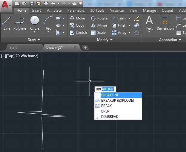
To create a Break line in AutoCAD
- Type BREAKLINE and press on the ENTER key on your keyboard
- Specify the starting point of the Break line
- Specify the ending point of the Beak line
- Specify the location of the break symbol
By default, the break symbol is located in the middle of the line. You can simply press the on the ENTER key on your keyboard at the end of step 3 to get the break symbol appear in the middle of the line.
While using the BREAKLINE command in AutoCAD, you have the following options you can make use of:
- Block
- Size
- Extension
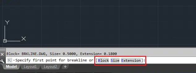
Where they respectively serve to 1. indicate the block to be used as the break line symbol if you would like to use another symbol different from the default one, 2. indicate the size of the breakline symbol if you would like the symbol to be larger or smaller than what it is by default, 3. indicate the length of the extension beyond selected end points.
It is also possible to create your own break line symbol using the Block option stated above.
To do so, you would have to create the symbol as a drawing, save that drawing in the Express folder of the AutoCAD installation folder and use it when needed utilizing the Block option of the BREAKLINE command.
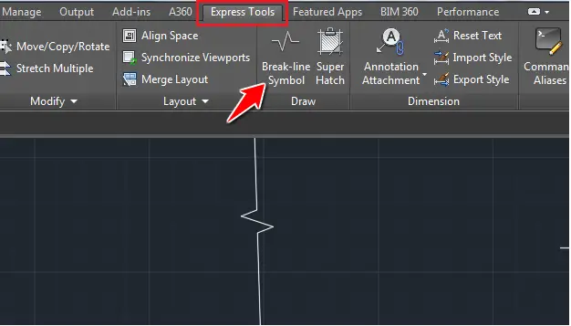
Using the Express Tools tab
You can also use the Express Tools tab to activate the BREAKLINE command.
Navigate to the latter, and click on the break-line Symbol.
Should you be interested in creating you own Break line symbol, visit this AutoCAD page.
3D Projects (Good 3D practice exercises)
- 3D Design project for beginners – AutoCAD
- An easy Modeling 3D project
- 3D Design project for beginners – A Stool
- 3D design project for Beginners – A table
- CAD projects for Beginners – Tinkercad
- Modeling a Vase with Tinkercad
- How to assemble with Tinkercad
- Beginner’s tips – Autodesk Tinkercad
- Design a mechanical part with Autodesk Tinkercad
- Modeling with AutoDesk Tinkercad
Related posts:
 AutoCAD Tutorial 00: AutoCAD Free Download Full Version
 AutoCAD and its Uses: What is AutoCAD Used for?
 Unique 2D Autocad Exercises to Improve Your Skill Now
 Learn AutoCAD Basics: DAY 4
 Learn AutoCAD Basics: DAY 13
 AutoCAD Tutorial 18: Basics of Annotation in AutoCAD
 The Best Way to Learn AutoCAD
 Convert DWG to STL