This post would be more interesting if you have checked the exercises where we first used the 3DRORATE command in AutoCAD.
Here we will be using the SWEEP command, just as the EXTRUDE command we have made use of when we built out first figure in AutoCAD, it helps obtain cylinders from circles and can do more.
The SWEEP command works with few differences as compared to the EXTRUDE command. It helps obtain 3D object from 2D object, just by indicating the path through which the 2D object is going to SWEEP to create the 3D object.
An easy example to demonstrate the possibilities of the SWEEP command is to build a 3D spring in AutoCAD using the SWEEP command and the HELIX command.
Going from the objects in Image 1 to Image 2.
Image 1
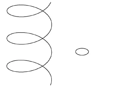
Image 2

Let’s use this opportunity to learn how to create an Helix in AutoCAD.
Create an helix in AutoCAD
- Type HELIX and press ENTER
- Specify the center point of the base
- Specify the value of the base radius
- Specify the value of the top radius
- Specify the height of the helix.
It is to be mentioned that there are many options you can make use of while using the HELIX command. Using this command you can build an helix based on the number of turns of the helix and/or the height-difference between two subsequent turns.
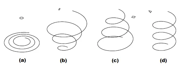
Here are few things you can build using the HELIX command
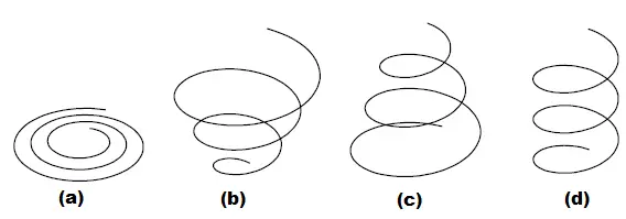
(a) Spiral
(b) Base radius smaller than top radius (spring)
(c) Base radius bigger than top radius (spring)
(d) uniform spring
SWEEP in AutoCAD
Let’s come back to the main topic of this post, which is the use of the SWEEP command in AutoCAD.
We have had a fun exercise using the 3DROTATE lately, we are right going to use the product of it to build the following 3D object in AutoCAD.
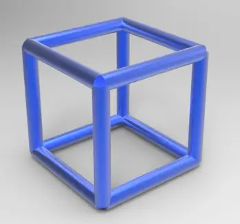
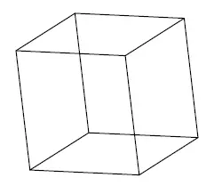
Using images on the left and the SWEEP command, we can build the image on the right.

Final object
How do you actually use the SWEEP command in AutoCAD.
- Type SWEEP and press ENTER
- Select object to sweep and press ENTER
- Select SWEEP path
As simple as that.
To build the image above
Step 1
We have 12 segments that will serve as SWEEP path (Use this post to learn how to get this object built)
Step 2
What we need now, is to draw a circle, duplicate it so to have 12 of them in total.
Step 3
Sweep 12 times, using each time a circle as the object to sweep and a segment as a sweep path.
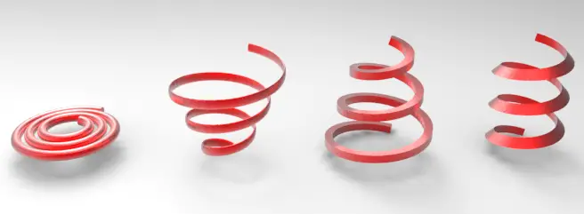
3D Spring
Coming back to our HELICES and let’s SWEEP them with objects having different shapes.
(a) Object to SWEEP: circle
(b) Object to SWEEP: Ellipse
(c) Object to SWEEP: Rectangle
(d) Object to SWEEP: Triangle
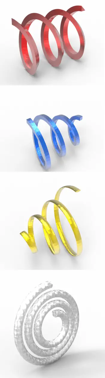
The resulting image
Additional images
3D Projects (Good 3D practice exercises)
- 3D Design project
- AutoCAD modeling project
- Creating A Stool in AutoCAD 3D
- Designing A table in AutoCAD
- CAD projects for Beginners
- Modeling a Vase
- How to assemble in Tinkercad
- Beginner’s tips – Autodesk Tinkercad
- Design a mechanical part with Autodesk Tinkercad
- Modeling with AutoDesk Tinkercad
Related posts:
 AutoCAD Tutorial 00: AutoCAD Free Download Full Version
 AutoCAD and its Uses: What is AutoCAD Used for?
 Unique 2D Autocad Exercises to Improve Your Skill Now
 Learn AutoCAD Basics: DAY 4
 Learn AutoCAD Basics: DAY 13
 AutoCAD Tutorial 18: Basics of Annotation in AutoCAD
 The Best Way to Learn AutoCAD
 Drafting a 3D Rectangle
Hi, after making a swept helix (similar to case b, being a spring with a smaller base radius and larger top radius), how can I determine the radius of curvature at any point along the spring? Also, is it possible to have the smaller radius end finish as a straight line?
It is not possible to determine the radius at every height level with the current version of AutoCAD as far as I know, But since you can determine the height, the number of turns, the base radius and the top radius I am sure there is a way you can figure out the radius at every height level.
As for finishing with a straight line, that is definitely possible.
How would I go about changing the end behaviors? I am trying to connect a conical helix with roughly 1 turn, to a cylinderical helix with multiple turns. I have attached a picture of the three components I am trying to connect smoothly. The radius of the cylinder will be the same as the top radius of the conical helix. The entire line will also be 1.5 inches wide, and hollow (inside diameter of 1). If you could help at all I would be very grateful.
https://uploads.disquscdn.com/images/a1aab4c24910e3a3bae47cc0a4b5a23fc69b1e015368128eb62255ac9a949986.png
This is a bit tricky. If I were you, I will try doing it in 3D and join both objects later. But still, the tricky part will be to join them, if the boundary is not smooth enough, it would not look as natural as you need it. That a tough one!