With this project, we are going to be working with a less popular sensor that we have been so far: the current sensor.
A current sensor can be super useful to monitor the amount of current that flows into a motor, for example, this can help avoid overloading your motor when it is in use and at the same time help preserve the motor from burning. You can also use a current sensor to calculate the energy consumption of a circuit.
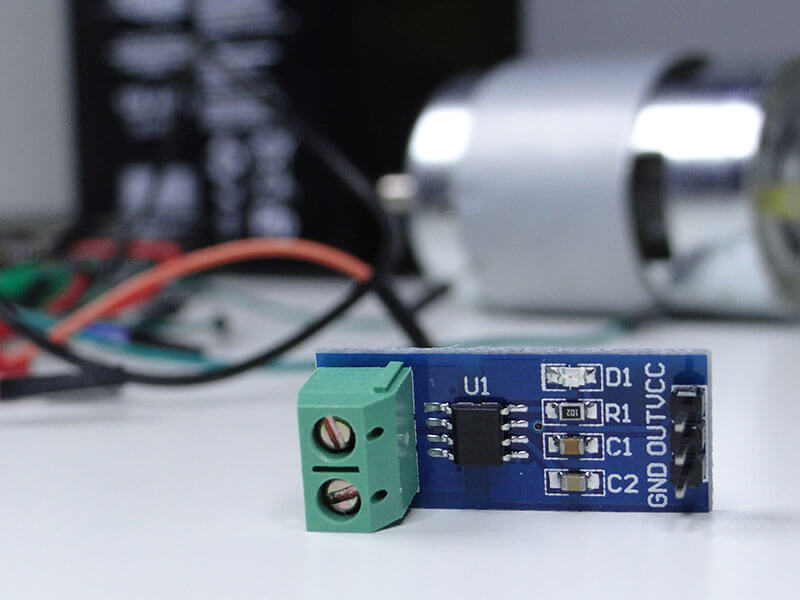
The name of the sensor we are going to use here is ACS712.
Let’s get started.
Parts needed
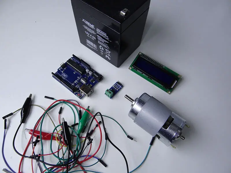
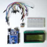
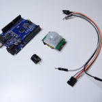
- 1 x Arduino Uno Board
- 1 x ACS712 current sensor (30A or 5A)
- 1 x Motor 775
- 1 x LCD Display with I2C converter
- 1 x Battery to power the motor
- Jumper wires
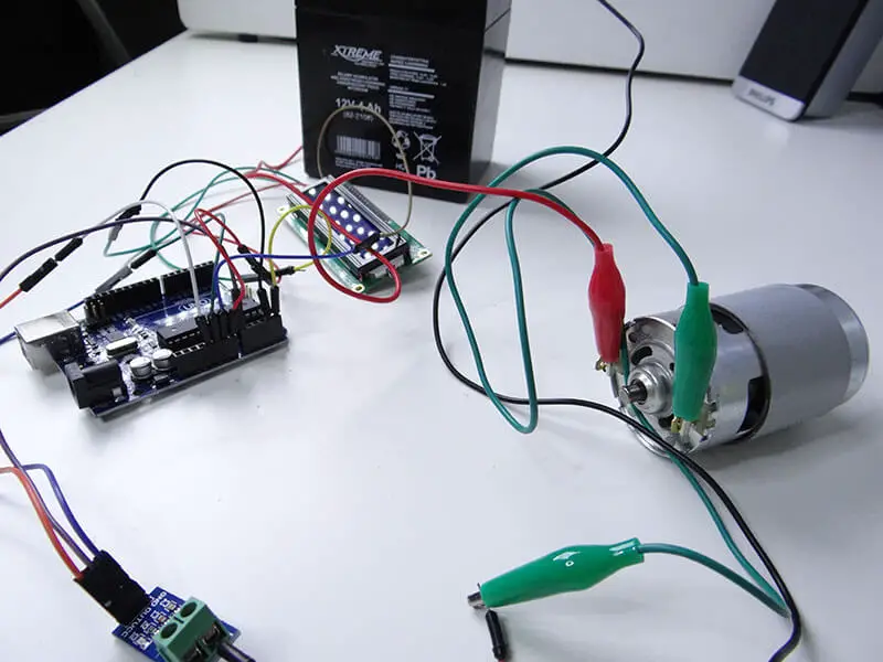
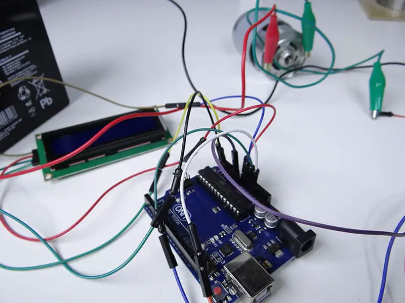
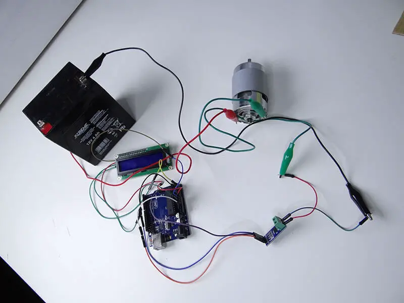
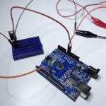
It is very useful to have jumper wires with alligator clips to make the connection of the motor to the battery easy.
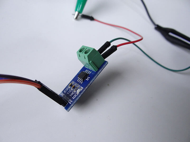
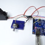
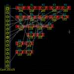
We will also need some male to female cables to connect the display and the sensor to the Arduino. There are no pins connected to the digital side of Arduino. We used one analog pin, SDA and SCL for the I2C communication with the display.
Keep in mind that on the schematic, the blue cables are GND and the red cables are VCC (5V).
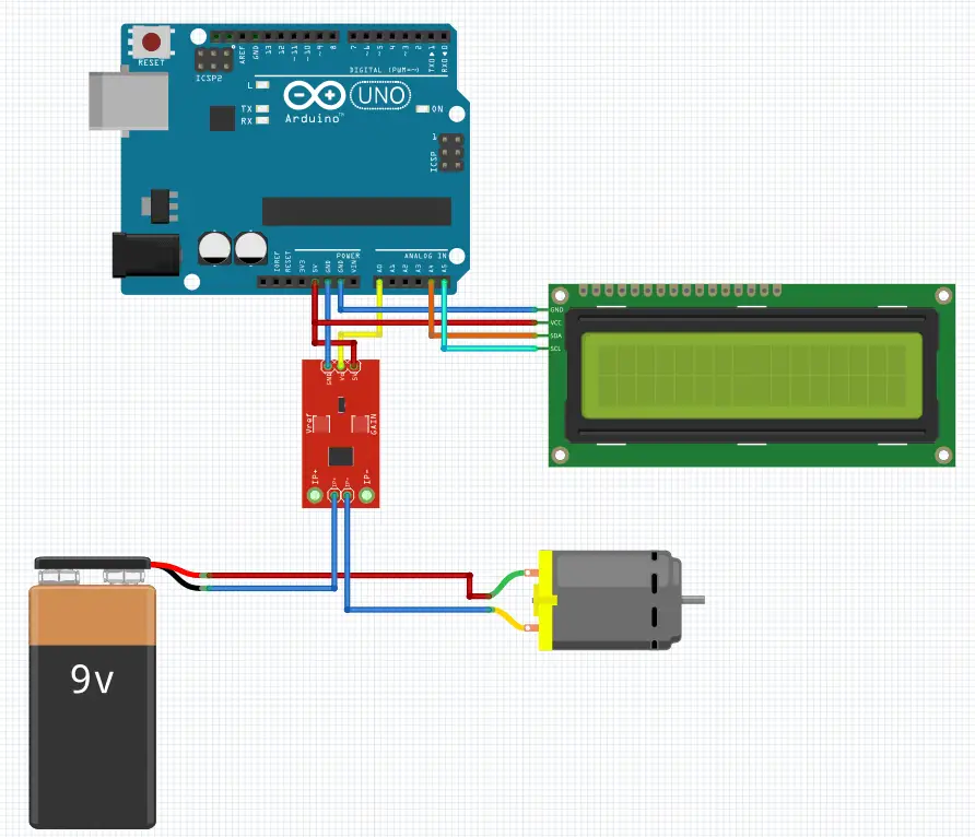
The 9V battery is for illustration purposes only, you can use any different battery as long as it fits with your the parameters of your motor.
When you are done connecting, upload the following code to the Arduino board.
To make our readings more reliable, we used the for loop to read the output of the sensor multiple times then output the average value. We’ve also subtracted 0.15 from the readings to serve as an error correction, thanks to this we have 0.00A when the current is not flowing through the circuit. You can see the result on the LCD but also on the serial monitor.
As you can see in the video below, I am trying to stop the shaft of the motor with my fingers and as a result of this, the current is increasing which is normal. You can also try working with a bigger motor or even building an Arduino current meter for your workshop.
That’s all for this Arduino project. Waiting to hear from you in the comment section below!
You might also like:
- Arduino hx711 tutorial
- Arduino magnetic switch
- Best Arduino Kits
- gifts for engineering students
- gifts for engineers
- mpu6050 Arduino projects
- Current sensor Arduino
- Soil Moisture Sensor With Arduino
- Arduino Count up Timer Using the Nokia 5110 LCD
- Arduino Yun: Integrating or Juxtaposing Arduino with Linux
- Arduino Projects: Line Follower Robot
- Arduino RFID Project for Beginners
- Arduino MOSFET Project
- Which Arduino Should You Buy
- What Can You Do With Arduino Boards?
- Great Alternatives to the Arduino Microcontroller
- Arduino Projects: Color Sensor
- Arduino IDE Alternatives
- Arduino Mega vs. Uno
- Arduino Projects: Arduino LCD Display
- Read Arduino Rotary Encoders
- A Selection of the Best Arduino Simulators
- Arduino Projects: IR Receiver
- Arduino Light Sensor Project
- Arduino Projects: Arduino Decibel Meter
- Arduino Stopwatch Project
- Arduino Bluetooth RC Car Project
- Arduino Temperature Logger Project
- Arduino Projects: Arduino 7 Segment Display
- Arduino Projects: Clap ON Clap OFF Light
- Arduino Relay Project
- Install a Library Onto the Arduino IDE
- Arduino Projects: Rainfall Detector
- Arduino Projects: RGB LED Arduino
- Arduino Stepper Motor Project
- Arduino Projects: Arduino DC Motor Control
- The Top Affordable Arduino Robot Kit
- Arduino 3D Printed Case
- Arduino Projects: Asynchronous LEDs Blink
- Arduino Projects: Ultrasonic Distance Sensor
- Arduino Projects: LED – 4X4X4 LED Cube
- Arduino Car Projects: Build an Obstacle Avoiding Robot With Less Than $30
- Arduino Projects: Servo Potentiometer Control
- Arduino LED Project: Knight Rider
- Arduino Projects: PIR Motion Sensor
- The Difference between Arduino and Raspberry Pi
- Top 9 Books Every Engineer Should Read
- Top Used Sensors for Arduino
- First Hand on the Arduino Uno Board
Related posts:
 Arduino Projects: Building an Arduino Countdown Timer
 Arduino Projects: LED – 4X4X4 LED Cube
 Arduino Projects: PIR Motion Sensor
 The Best Arduino Starter Kits
 Arduino Relay Project
 Arduino Projects: Building a Mini Arduino Shield With KiCAD – Part 1
 Arduino MOSFET Project
 The Top Alternative IDE for Arduino You Should Start Using Today